2-12
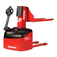
Description - STACKY 2012.12
13 - CHARGE INDICATOR
This shows the level of charge of the batteries, indicated by ve green LEDs, two yellow
LEDs and three red LEDs. Alternately ashing red LEDs indicate that the minimum
charge has been reached.
14 - EMERGENCY STOP BUTTON
This device stops stacker movements in emergency situations. Pull the button to restart
the stacker. For safety, push in the emergency stop button when the stacker is switched o.
15 - KEY SWITCH
To use the stacker, insert the key in the switch and turn clockwise. Pull the emergency
stop button if it has been actuated.
16 - CARRIAGE
The carriage is a component that slides in the moving frame or the chassis. The tool is
attached to this carriage by a hook and two M10 screws.
17 - LIFTING CHAIN
One end of the chain is attached to the cylinder and the other to the carriage. It runs inside the chassis and passes over a pulley
located above the cylinder. Its tension must be checked before using the stacker.
18 - CHARGING LEAD
The charging lead is inserted into a dummy socket. If it is not in place, a safety system prevent the stacker from being used.
It is therefore essential that the charging lead is properly plugged-in to the dummy socket after recharging the battery.
19 - “DOWN” BUTTON
The lowering of the forks or the tool is controlled by these buttons that are accessible for both left and right hand use.
20 - “UP” BUTTON
The raising of the forks or the tool is controlled by these buttons that are accessible for both left and right hand use.
21 - CRAWL (TORTOISE) BUTTON
This button allows the stacker to travel at low speed. This function is very useful when manoeuvring in conned spaces.
When this button is operated, the stacker travels at 30 % of its nominal speed. This control is used in addition to the motion
controls. This function can be used regardless of the tiller arm position.
22 - HORN BUTTON
23 - BUTTERFLY CONTROL SWITCHES
To move the stacker, gradually push one of the buttery control switches up or down according to the chosen direction of travel.
They only work when the tiller arm is in the driving zone (2) (g. 4).
As the stacker is equipped with a speed controller, its speed is progressive and increases according to the angular position
of the buttery control switch.
To stop the stacker, release the buttery control switch, which will return to the neutral position, gradually bringing the stacker
to halt.
24 - ANTI-CRUSHING SAFETY DEVICE
The end of the tiller arm is equipped with an anti-crushing safety device, that protects the operator by reversing the direction
of travel for a few seconds as soon as it is pushed. This only applies when the stacker is in forward mode.
25 - HYDRAULIC UNIT
The hydraulic unit consists of an electric motor, a hydraulic pump, an electrovalve, a pressure limiter and an oil tank. This hydraulic
unit operates the cylinder that raises the fork or the tool.
26 - OIL TANK
This tank contains the oil necessary for the operation of the hydraulic unit.
27 - ELECTRONIC SPEED CONTROLLER
The electronic speed controller progressively increases the speed of the stacker according to the angular position of the buttery
control switch. It also allows a progressive raising/lowering motion.
28 - SWITCH
The hydraulic pump is powered via this switch. It is controlled by the “up” buttons (20).
29 - CHARGER
The stacker is equipped with a charger that transforms the 220 V - 50 Hz voltage into a DC voltage suitable for charging the
batteries. Charging stops automatically the moment the batteries are recharged. An indicator lamp located next to the lead
(18) indicates the battery charge level.
VOLTS
28
22
19
16
-
+
13