HYDRAULIC SYSTEM 14000 SERVICE MANUAL
2-22
Published 09-10-14, Control # 065-24
Before replacing a pressure sender, do the following:
- Perform pressure sender test.
- Attach an accurate hydraulic pressure gauge to the
quick-coupler at the suspect pressure transducer
(see Section 2 of the Service Manual).
- If pressure appears on the gauge, bleed the
corresponding system so the gauge reads zero
pressure.
- Repeat pressure sender test and check pressure on
the display with the engine running at idle - the
display reading and the gauge reading should be
the same.
- Before replacing a pressure sender, check the
signal voltage at the sender. It should be 1.00 volt
against ground at 0 psi.
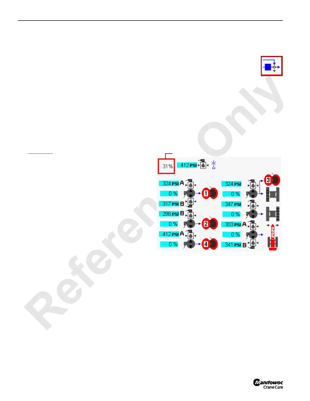
Control Calibration
See Figure 2-22 for the following procedure.
Control calibration calculates the pump threshold command
level for all drum and swing functions.
Perform this calibration when:
- A new pump or motor is installed in a drum or swing
function.
- A new master node or master node software is
installed.
- Operation indicates threshold is in error.
- Excessive handle motion or time required to
initiate motion.
- Inability to start motion smoothly.
Calibrate controls as follows:
1. Apply all park brakes with switches on control console.
2. Start and run the engine at high idle.
3. Press Enter button to go to Pressure Test and
Calibration screen from Menu screen.
4. Press Enter button to go to level 2. Use
Select buttons to show CONTROL
CALIBRATION icon in data box.
5. Press Confirm button to start test.
6. Calibration starts and percent of completion is displayed
in data box.
7. When calibration is complete, control calibration icon
reappears in data box.
Pump threshold command levels must be within a
specified range during this test. Any pump requiring a
threshold command level outside this range is
highlighted yellow. Troubleshoot failed circuit to
determine cause of fault.
FIGURE 2-22
14COM3-52
DDData Box
 Loading...


