ELECTRIC SYSTEM 14000 SERVICE MANUAL
3-40
Published 09-10-14, Control # 065-24
CAN Bus Screen
See Figure 3-32 for the following procedure.
The CAN bus diagnostic screen is for technicians. The
screen displays CAN bus packet and node information,
engine status, history status, and boom status. Any node that
is yellow indicates that communication is lost to that node.
The CAN Bus screen operates on two levels:
Level 1 — Packet number data box highlighted blue
Level 2 — Packet number data box highlighted red
Packet Information
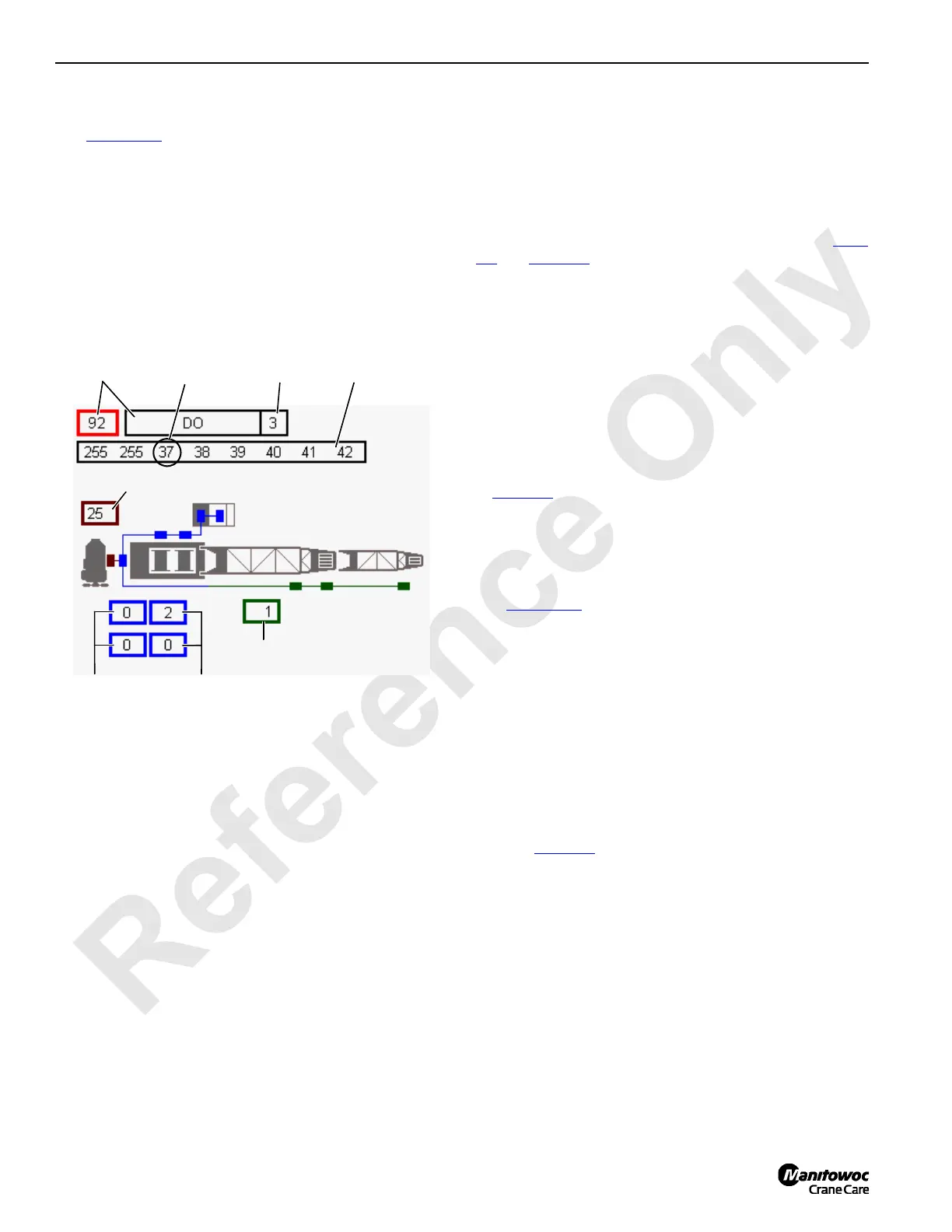
The top row of the screen contains CAN Bus packet number
(92). Enter desired packet number in the first data box by
using Select buttons.
Packet type (AI) is displayed on top middle data box.
Related node (3) is indicated in top last data box.
Packet contents is displayed in the eight banks under the
row. Packet content and format depends on packet type.
Many packets are not easily interpreted by other than factory
technical personnel and their content is not discussed in this
publication.
Each individual input/output is assigned a number (identifier)
in the binary system (powers of two). The identifiers of all
inputs/outputs that are ON (active) for each bank are added
for a total of 0 – 255. The number displayed for each bank is
the sum of all identifiers that are ON in that bank. Each
possible ON/OFF combination per bank has a unique total.
To determine the status of an individual digital input or
output, you need to know the CAN packet number (see Table
3-3 and Table 3-4). For example: Drum 1 Park Switch has a
packet number of CAN92-3-4.
The first part of the number – CAN92 – indicates that the
individual input or output is located in packet 92 of CAN
communications.
The second part of the number – 3 – indicates the bank
where the individual information is shown on the CAN
screen.
The third part of the number – 4 – is the item identifier.
Determine status of the individual input/output by checking
the total in bank three (37). Find 37 in the numbered column
of Table 3-8
- Bank Identifier Numbers. In the corresponding
row the identifier numbers that are ON in the bank are
shaded (1, 4, 32). In the above example identifier 4 is shaded
so Drum 1 Park Switch is ON.
Digital Output Disable Fault
See Figure 3-32 for the following procedure.
The control system is capable of detecting an open or short
circuit in most of the system’s digital outputs. When Fault 84-
Digital Output Disable is shown in fault section of
Information screen, using following procedure:
1. Scroll through packet numbers 30, 31 and 33.
2. Banks 1, 2 and 3 of CAN screen should display number
255.
3. If a number less than 255 is displayed in banks 1, 2, and
3, use the Bank Identifier Numbers in Table 3-8 to
determine which bit(s) are off.
4. Use Table 3-7
Digital Output Disable, to determine what
outputs are not working.
5. Investigate indicated outputs for short to ground, short to
shield or other problem.
Engine Node Status
Displays engine node bus status. This information is for
factory use only. The number displayed should be under 64.
8 Packet
Number Banks
Engine Node Status
Crane History
Status
Boom Node
Status
Packet
Number &
Type
FIGURE 3-32
Node
Number
Crane
Status
14COM3-50
Bank 3
Tot al

 Loading...


