Manitowoc Published 09-10-14, Control # 065-24 5-5
14000 SERVICE MANUAL HOISTS
SPEED SENSOR ADJUSTMENT
General
The hydraulic motor for each hoist drum has a speed sensor.
Each speed sensor monitors rotational speed and direction
of the corresponding function’s motor. The sensor sends a
signal to a remote node controller that transmits information
to the crane’s master controller. The master controller uses
this information to control crane functions.
Speed Sensor Replacement
When removing the speed sensor from a motor, be careful to
contain the hydraulic fluid that will drain from the motor. After
installing a new sensor, add clean hydraulic oil to the level of
the motor’s top case drain port before starting the engine.
Speed Sensor Adjustment
Speed sensors are set at the factory and should not need
adjustment, unless replaced.
1. Bring corresponding function to a complete stop, land
suspended load if load drum is being serviced, and
PARK function.
2. Remove faulty sensor. Do not connect sensor cable to
crane wire harness until initial adjustment is made.
3. Loosen lock nut and carefully turn sensor in (clockwise)
by hand until it gently contacts speed ring inside motor.
4. Back sensor out one turn or more until notch is
positioned 180° from motor shaft (facing outboard side
of motor).
5. Connect sensor cable to crane wire harness.
6. Operate drum motor and check for a steady drum speed
(RPM) signal on corresponding drum’s diagnostic
screen in cab.
If necessary, turn sensor out slightly until drum speed
(RPM) is steady at low and high RPM.
7. Hold sensor in position and securely tighten lock nut.
WARNING
Burn Hazard!
Hot oil will drain from motor port when sensor is removed.
Wait for hydraulic oil to cool before removing sensor.
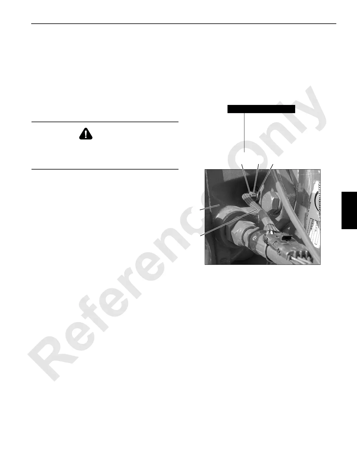
P2196
Typical Speed Sensor Installation
at Drums 1, 2, 3 and 4
FIGURE 5-4
Item Description
1 Speed Sensor
2Notch
3 Lock Nut
4Cable
5 Motor
4
1
5
2
3

 Loading...


