ELECTRIC SYSTEM 14000 SERVICE MANUAL
3-36
Published 09-10-14, Control # 065-24
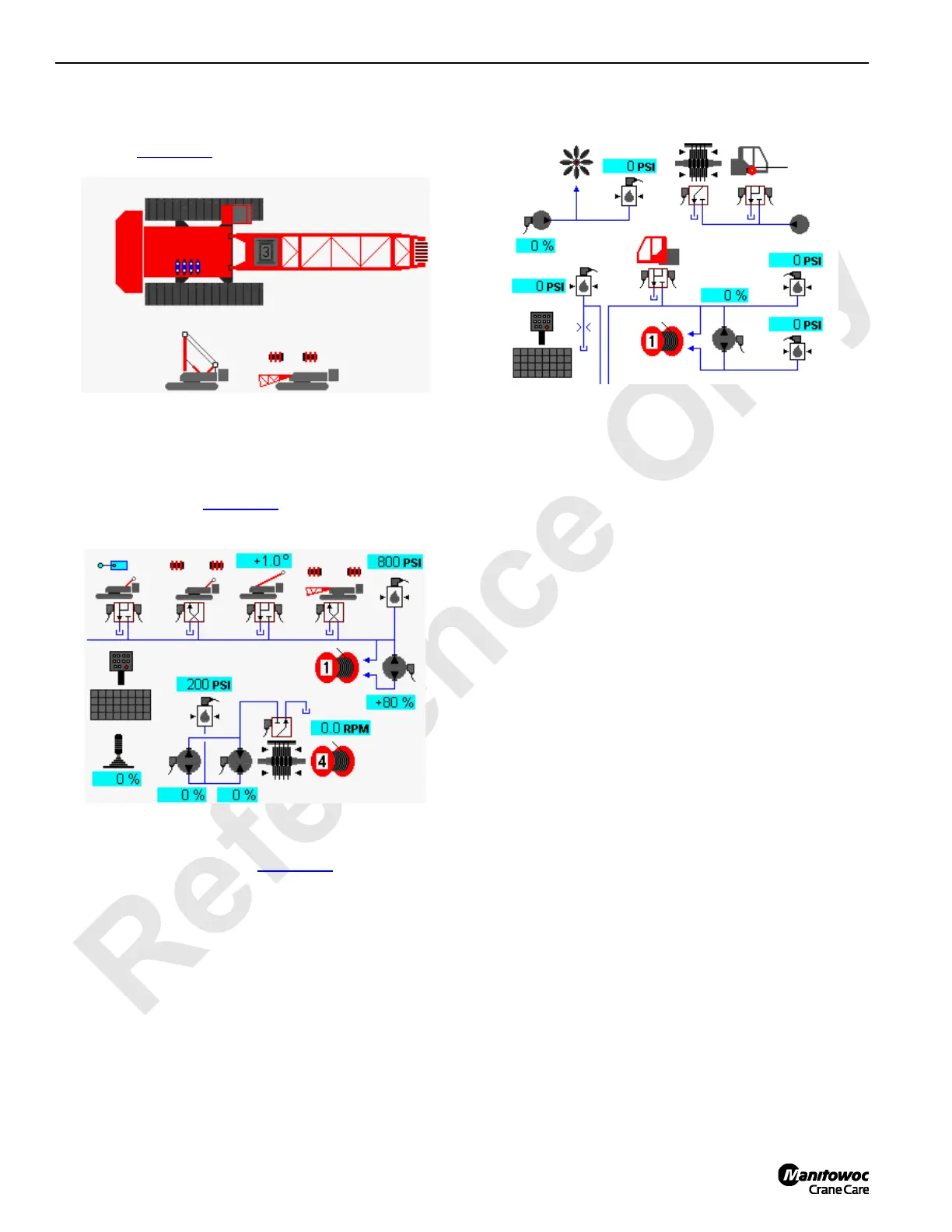
Accessory Diagnostic Screen
Select mast cylinders and boom pin icons in screen level 1
as shown in Figure 3-17
. Press Enter button to go to level 2.
In level 2, there are two diagnostic screens.
In diagnostic screen one, gantry cylinders up/down with up
limit switch, back hitch pins, mast arm cylinders and boom
hinge pins are shown (Figure 3-18
).
In diagnostic screen two, rigging winch, cab tilt and the
cooling fan system are shown (Figure 3-19
).
Function Mode Screens
The Function Mode screens are used to enable/disable
modes and to set operating parameters for the individual
crane functions. This screen operates on four levels.
Level 1— Image of overall crane shown. Use Select buttons
to highlight individual crane functions.
Level 2 — Shows function mode screen for highlighted
crane function. The selected mode or limit data box is
highlighted blue. Use Select buttons to choose a mode or
limit data box.
Level 3 — The selected mode or limit data box highlighted
red. Use Select buttons to enable/disable a mode or to set a
limit.
Level 4 — The selected mode or limit data box highlighted
green. Use Select buttons to adjust the value, shown in data
box.
To enable/disable modes or to set operating parameters for
individual crane functions:
1. Press Enter or Exit buttons as required to go to level 1.
Use Select buttons to highlight desired crane function.
2. Press Enter button to go to level 2. Use Select buttons
to choose the mode or limit data box to access. Press
Enter button to go to level 3.
3. Use Select buttons to enable/disable mode or to adjust
operational parameter.
4. Press Enter button to go to level 4 if required. Use
Select buttons to adjust operational parameter.
5. Press Exit button as required to return to a previous
level or to the Menu screen.
The yellow alert symbol is displayed if a system fault occurs.
See Information screen to access faults.
FIGURE 3-18
14COM3-40
Mast Selected
 Loading...


