Manitowoc Published 09-10-14, Control # 065-24 3-17
14000 SERVICE MANUAL ELECTRIC SYSTEM
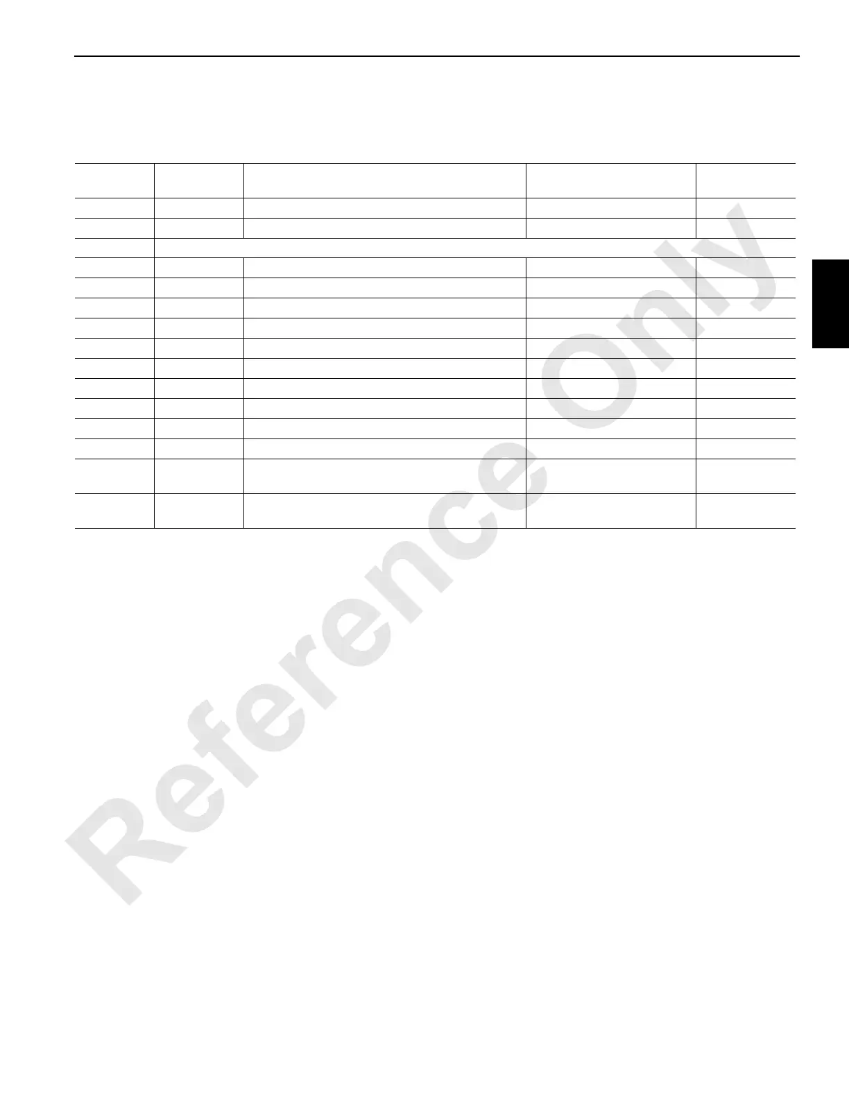
Node 5 — Swing Limits (Optional)
See Electrical Schematic A17144, Sheets 11, 17 and 19 (at the end of this section).
Receptacle
Number
Function
Type
Description Test Voltages
CAN Packet
Number
J1-WN04
I/O Cable — From Node 3 N/A
J7-WN06
I/O Cable — To Node 4 N/A
J6/W56 Receptacle – Swing Limits, Air Temperature Sender
56-D DO-8
Air Temperature Sender or Terminal Plug 24 Volts Nominal CAN29-1-128
56-E Ground
Swing Motor Encoder Ground
56-F DO-9
Swing Motor Encoder 24 Volts Nominal CAN29-2-1
56-H DO-10
Swing Limit Switch 24 Volts Nominal CAN29-2-2
56-J DI-8
Right Swing Limit Switch 0 Volts Off, 24 Volts On CAN55-1-128
56-N NS4
Node Select 5 Jumper to Ground 0 Volts (With Jumper)
56-P DI-7
Left Swing Limit Switch 0 Volts Off, 24 Volts On CAN55-1-64
56-U Ground
Ground to Node 4 Ground
56-W Ground
Air Temperature Sender or Terminal Plug Ground
56-b AI-10
Air Temperature Sender or Terminal Plug 0 Volts Off, 24 Volts On CAN18-4
56-n EC1A
Swing Motor Encoder
1.2 or 3.2 Volts Not Moving;
2.2 Volts Moving
CAN43-1
56-p EC1B
Swing Motor Encoder
1.2 or 3.2 Volts Not Moving;
2.2 Volts Moving
CAN43-1
 Loading...


