Manitowoc Published 09-10-14, Control # 065-24 5-9
14000 SERVICE MANUAL HOISTS
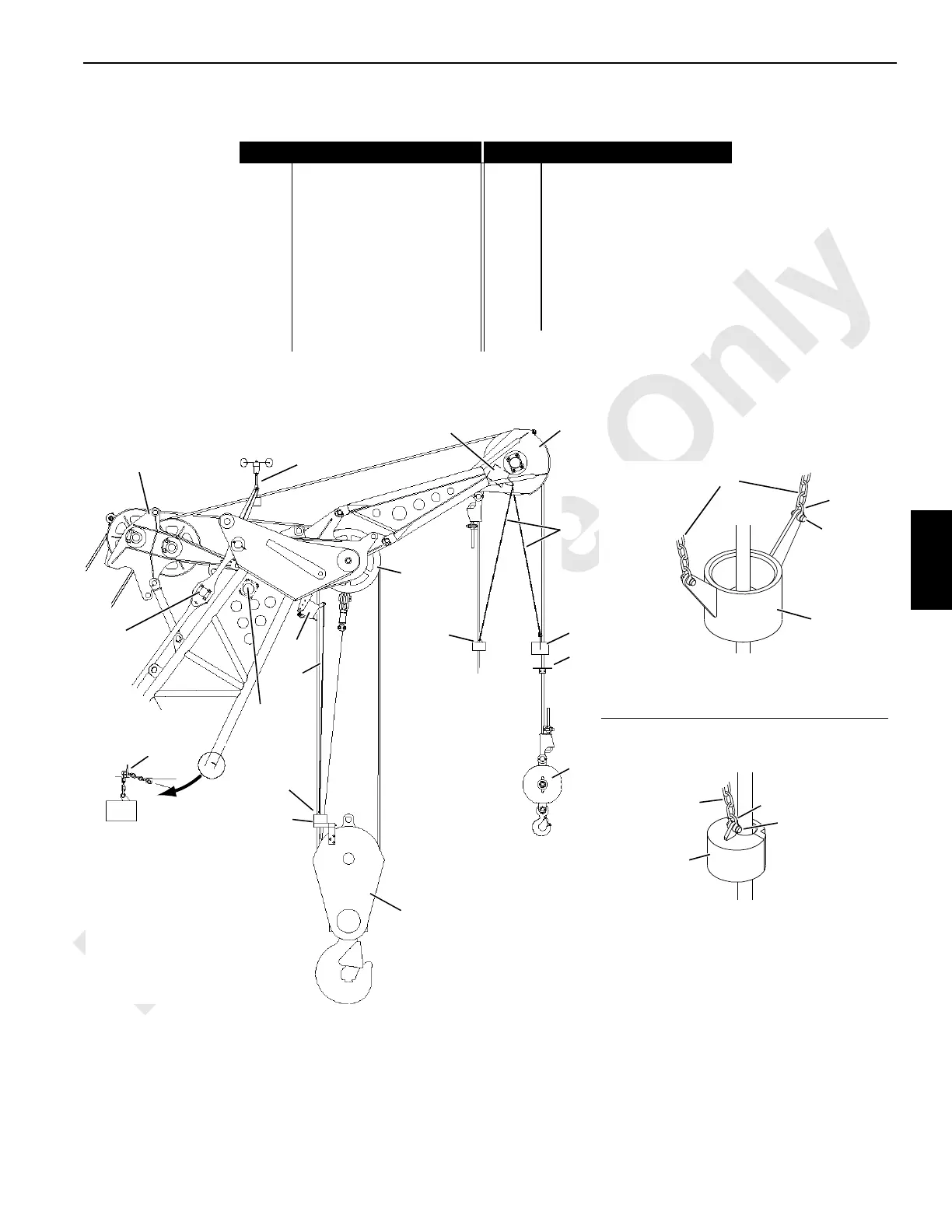
FIGURE 5-6
6
Item Description Item Description
1 Wire Rope Guide 10 Upper Boom Point
2 Load Cell (RCL) 11 Weight
3 Wind Speed Transmitter 12 Lift Block
4 Lower Boom Point 13 Weight Ball
5 Block-Up Limit Switch 14 Shackle
6Chain 15Pin
7 Weight 16 Boom Node
8 Lift Block 17 Lug (weight storage)
9 Load Block
1
10
2
5
5
3
6
7
8
Multiple Part Reeving
Dead Ended at Block
9
Single Part
Reeving
2-Part
Reeving
Location of Components at Boom Top Shown
Location of Components at Jib Tops is Similar
See Load Block Reeving Diagrams for
Suggested Location of Weight with
Multiple Part Reeving
4
11
12
13
7
14COM4-164
16
17
• Lower Boom Point (multiple part)
• Lower Boom Point (two lines over point)
• Upper Boom Point (1-part)
• Fixed Jib Point (2-part)
Dead-End Load Line or
Slowest Live Line
6
7
14
15
• Upper Boom Point (1-part)
• Fixed Jib Point (1-part)
• Luffing Jib Point (1-part)
6
11
14
15
A1284
 Loading...


