Manitowoc Published 09-05-14, Control # 226-02 2-29
14000 SERVICE MANUAL HYDRAULIC SYSTEM
Motor Leakage Test
Perform the following test if troubleshooting indicates the
need:
• Low Charge Pressure
• Sluggish Operation
• Excessive Heat
See Figure 2-28
for following procedure.
1. Stop engine.
2. Install an accurate flow meter in highest case drain port
(see Figure 2-13
) at desired motor.
• A 3,000 psi (207 bar) in-line meter with a flow rate of
30 gpm (114 L/m) is required.
• All motors except swing require 16 ORS fittings.
Swing requires 12 ORS fittings.
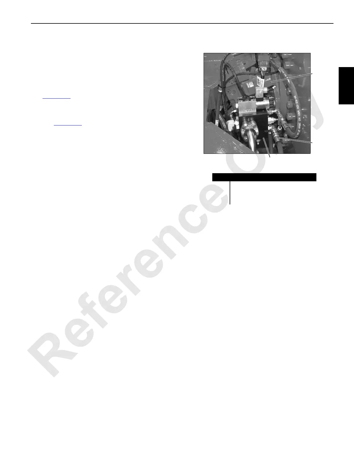
3. For hoist motors only, disable loop flushing as follows:
a. Disconnect loop flushing hose (2) from elbow in loop
flushing valve (1).
b. Install an 08 ORS cap on end of elbow and an 08
ORS plug in end of hose.
4. Start and run engine at high idle.
5. Monitor flow meter. Under all operating conditions,
leakage should not be more than 1-1/2 to 2-1/2 gpm (5.7
to 9.5 L/m.
6. Stop engine and enable loop flushing by reconnecting
hose to elbow in loop flushing valve.
7. Start and run engine at high idle.
8. Monitor flow meter. Under all operating conditions,
leakage should not be more than 5-1/2 to 6-1/2 gpm (21
to 24 L/m).
9. If motor leakage without loop flushing is not within
specified range, replace motor and pump.
10. If motor leakage with loop flushing is not within specified
range, replace loop flushing valve and/or motor and
pump depending on which is the cause for high leakage.
FIGURE 2-28
Typical Motor Installation
Item Description
1 Loop Flushing Valve
2 Loop Flushing Hose
3Motor
1
2
3
P2297b
 Loading...


