Manitowoc Published 09-05-14, Control # 226-02 3-29
14000 SERVICE MANUAL ELECTRIC SYSTEM
Cab Tilt Status
Displays command state of cab tilt cylinder —
cab up or down (shown).
Boom Hinge Pin Status
Displays command state of boom hinge pin
cylinders — extended (shown) or retracted.
Cooling Fan Status
Displays command state of cooling fan speed
status as a percentage of maximum rpm.
Engine Diagnostics
See the 14000 Operator Manual.
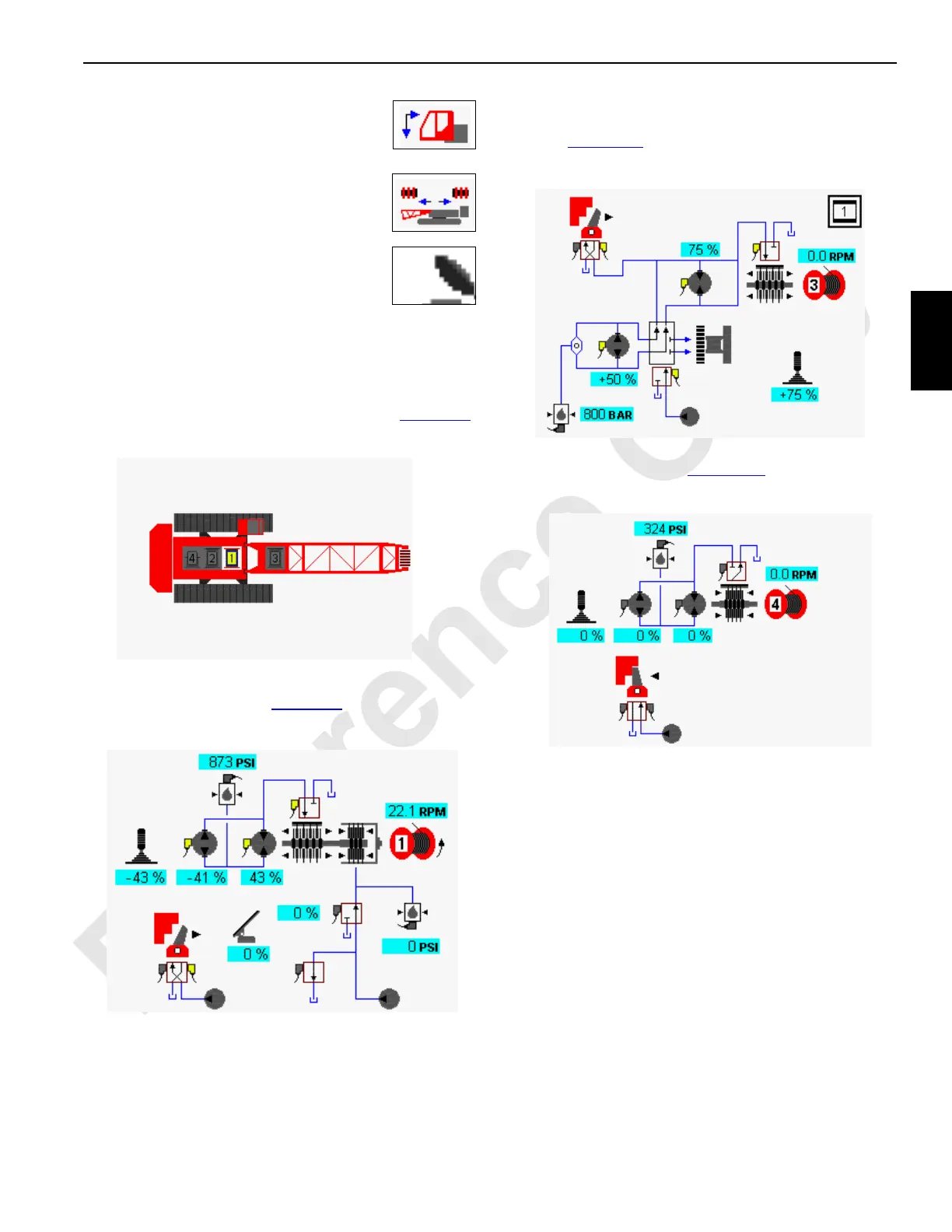
Drum Diagnostic Screens
Select drum icon in screen level 1 as shown Figure 3-8.
Press Enter button to go to level 2.
In drum example shown in Figure 3-9
, drum 1 function is
shown lowering. Load drum 2 operation is similar.
For load drum 3, left travel pump is dedicated to operate
drum 3 motor through diverting valve when drum 3 is
selected (Figure 3-10
). Drum 3 is inoperable when traveling.
Drum 3 can be configured as load drum or luffing jib.
In drum example shown in Figure 3-11
, drum 4 function is
shown not operating.
FIGURE 3-8
Diagnostic Screen
Drum 1 Selected
14COM3-31
FIGURE 3-9
Drum 1
14COM3-32
FIGURE 3-10
Drum 3
14COM3-33
FIGURE 3-11
Drum 4
14COM3-34
 Loading...


