INTRODUCTION 14000 SERVICE MANUAL
1-42
Published 09-05-14, Control # 226-02
DRUM 1 AND DRUM 2 - FREE FALL
(OPTIONAL)
See Figures 1-23, 1-24, and 1-25.
The front drum, rear drum or both drums can be equipped
with free fall option. In free fall, the left clutch/brake pedal
operates the front drum while right clutch/brake pedal
operates the rear drum when lowering the load. When
hoisting in free fall, the drum control handles operate the
same as in normal operation. See Drum 1 and Drum 2
System topics for a description of front and rear drum
operation.
An engine-driven hydraulic gear pump supplies hydraulic
fluid at 3,000 psi (207 bar) to operate front/rear drum free fall
systems.
When free fall is not active, hydraulic fluid flows through the
freefall enable directional control valve to tank. System
pressure is not high enough to release spring-applied clutch/
brakes. A pressure sender for each free fall drum in manifold
provides system pressure information to node-1 controller.
Front or rear drum pump and motor case drains are
connected together and routed to system drum clutch/brake
housing. Case drain cooling fluid enters the center of clutch/
brake housing and exits at top of housing. From clutch/brake
housing outlet the cooling fluid returns to tank.
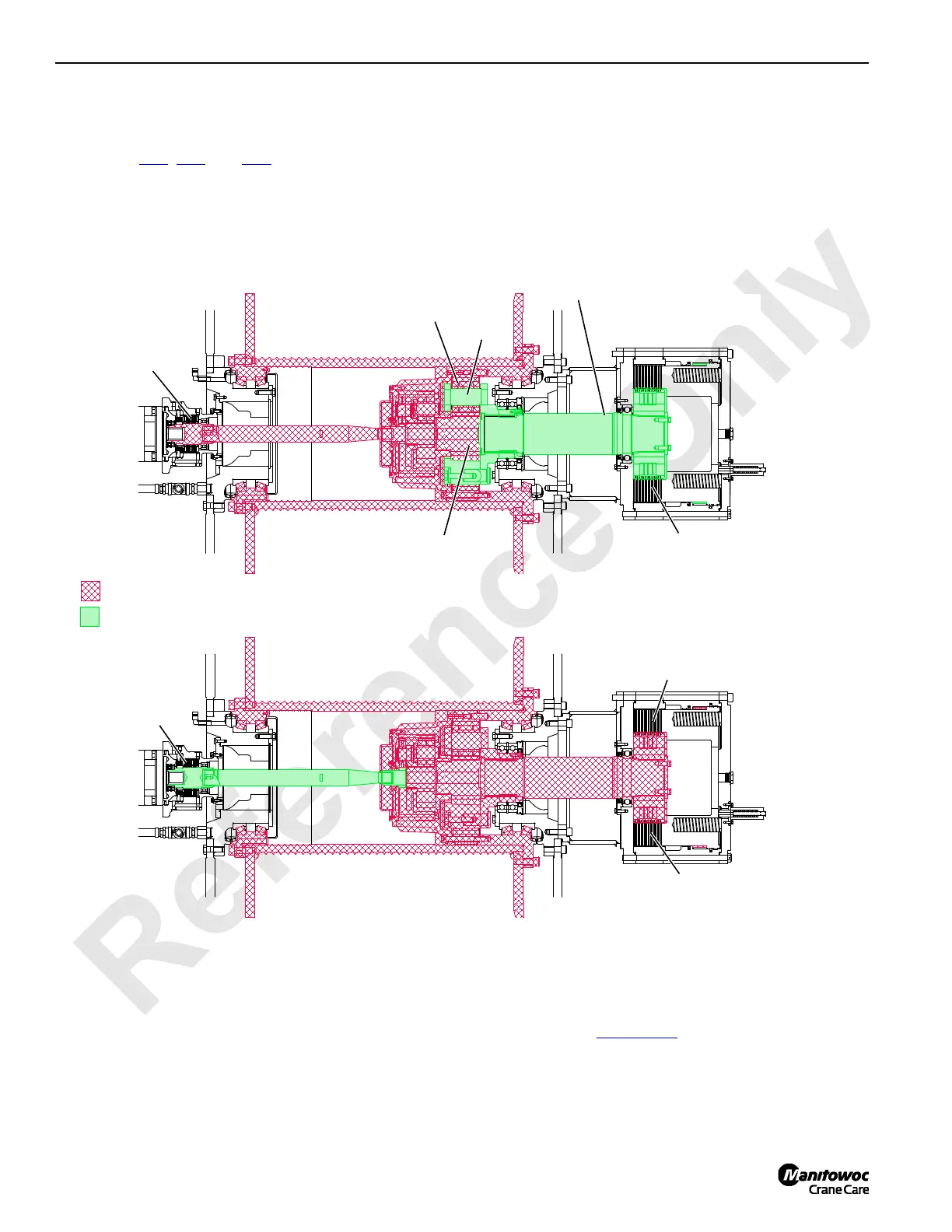
When clutch/brake is applied, the shaft is engaged with drum
planetary gears (Figure 1-23
). In full power, the drum is
powered from the motor shaft through planetary gears to
rotate the drum. The free fall clutch/brake shaft is attached to
the third planet gear carrier and does not rotate when
operating in full power.
FIGURE 1-23
Free Fall Operation
Free Fall Clutch/
Brake Shaft
RG-16
Rotating Components
Sun Gear
Stationary Components
RG-17
Full Power Operation
Friction Discs Rotate
Planetary
Carrier
Friction Discs and Outer
Plates Stationary
Free Fall Clutch/Brake
Engaged
Drum Brake
Released
Free Fall Clutch/Brake
Disengaged
Drum Brake
Engaged
 Loading...


