ELECTRIC SYSTEM 14000 SERVICE MANUAL
3-36
Published 09-05-14, Control # 226-02
CAN Bus Diagnostic Screen
See Figure 3-31 for following procedure.
The CAN bus diagnostic screen is for technicians. The
screen displays CAN bus packet and node information,
engine status, history status, and boom status.
The CAN Bus screen operates on two levels:
Level 1 — Packet number box highlighted blue.
Level 2 — Packet number box highlighted red.
Packet Information Boxes
The first box of the top row the example screen contains the
Packet Number. Enter the desired packet number by using
Select buttons.
Packet Type (DO, DI, AO, AI, ENC, or PWM) is displayed on
top middle data box.
The associated Node (3) is indicated in top right data box.
In the box in the second row, the content of the packet is
displayed in eight “banks.” Cross-reference the number that
appears in a bank to Table 3-8
to determine the identity or
status of the associated input or output.
Each input or output is assigned a number (identifier) in the
binary system (powers of two):
- The identifiers of all inputs/outputs that are ON
(active) for each bank are added for a total of 0–255.
- The number displayed for each bank is the sum of
all identifiers that are ON in that bank.
- Each possible ON/OFF combination per bank has a
unique total.
Many packets are not easily interpreted by other than factory
technical personnel and their content is not discussed in this
publication.
Also see Using the CAN Bus Screen to Troubleshoot a
Digital Output Fault on page 3-37.
Engine Node Status Box
Displays engine node (ECM) bus status. This information is
for factory use only. The number displayed should be under
64.
Crane Status Box
Displays crane errors. The number displayed in top box
corresponds to the following:
• Number 0 = Crane status normal.
• Number 1 = Node 2 is not communicating.
• Number 2 = Node 3 is not communicating.
• Number 4 = Node 4 is not communicating.
• Number 8 = Node 5 is not communicating.
• Number 32 - Bin node is not communicating.
• Number 64 - RIN (remote input node) node is not
communicating.
• Number 128 = Engine node is not communicating.
NOTE: The bottom box is not used at this time.
Status History Box
Errors since power was last cycled.
Banks (8)
Engine Node Status
Crane Node
Error History
Boom Node
Status
Packet
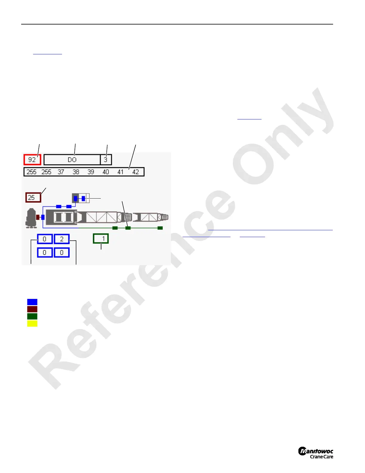
Number
FIGURE 3-31
Node
Crane Node
Status
14COM3-50
Node Map
Node Map Color Key
• Blue = crane/engine node
• Brown = engine ECM
• Green = boom, fixed jib, luffing jib nodes
• Yellow = a non-communicating node
Packet
Type
Packet
Information
Rows

 Loading...


