Manitowoc Published 09-05-14, Control # 226-02 3-17
14000 SERVICE MANUAL ELECTRIC SYSTEM
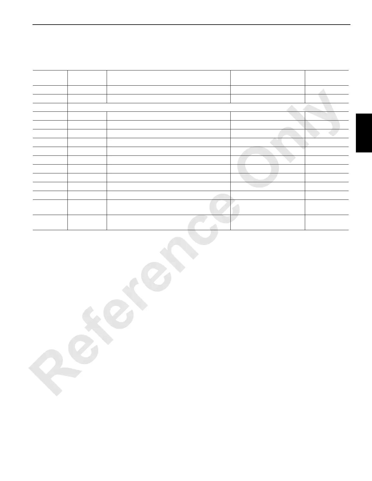
Node 5—Swing Limits (Optional)
See Electrical Schematic A17144, Sheets 11, 17 and 19 (at end of this section).
Receptacle
Number
Function
Type
Description Test Voltages
CAN Packet
Number
J1-WN04
I/O Cable — From Node 3 N/A
J7-WN06
I/O Cable — To Node 4 N/A
J6/W56 Receptacle – Swing Limits, Air Temperature Sender
56-D DO-8
Air Temperature Sender or Terminal Plug 24 Volts Nominal CAN29-1-128
56-E Ground
Swing Motor Encoder Ground
56-F DO-9
Swing Motor Encoder 24 Volts Nominal CAN29-2-1
56-H DO-10
Swing Limit Switch 24 Volts Nominal CAN29-2-2
56-J DI-8
Right Swing Limit Switch 0 Volts Off, 24 Volts On CAN55-1-128
56-N NS4
Node Select 5 Jumper to Ground 0 Volts (With Jumper)
56-P DI-7
Left Swing Limit Switch 0 Volts Off, 24 Volts On CAN55-1-64
56-U Ground
Ground to Node 4 Ground
56-W Ground
Air Temperature Sender or Terminal Plug Ground
56-b AI-10
Air Temperature Sender or Terminal Plug 0 Volts Off, 24 Volts On CAN18-4
56-n EC1A
Swing Motor Encoder
1.2 or 3.2 Volts Not Moving;
2.2 Volts Moving
CAN43-1
56-p EC1B
Swing Motor Encoder
1.2 or 3.2 Volts Not Moving;
2.2 Volts Moving
CAN43-1
 Loading...


