Manitowoc Published 09-05-14, Control # 226-02 3-3
14000 SERVICE MANUAL ELECTRIC SYSTEM
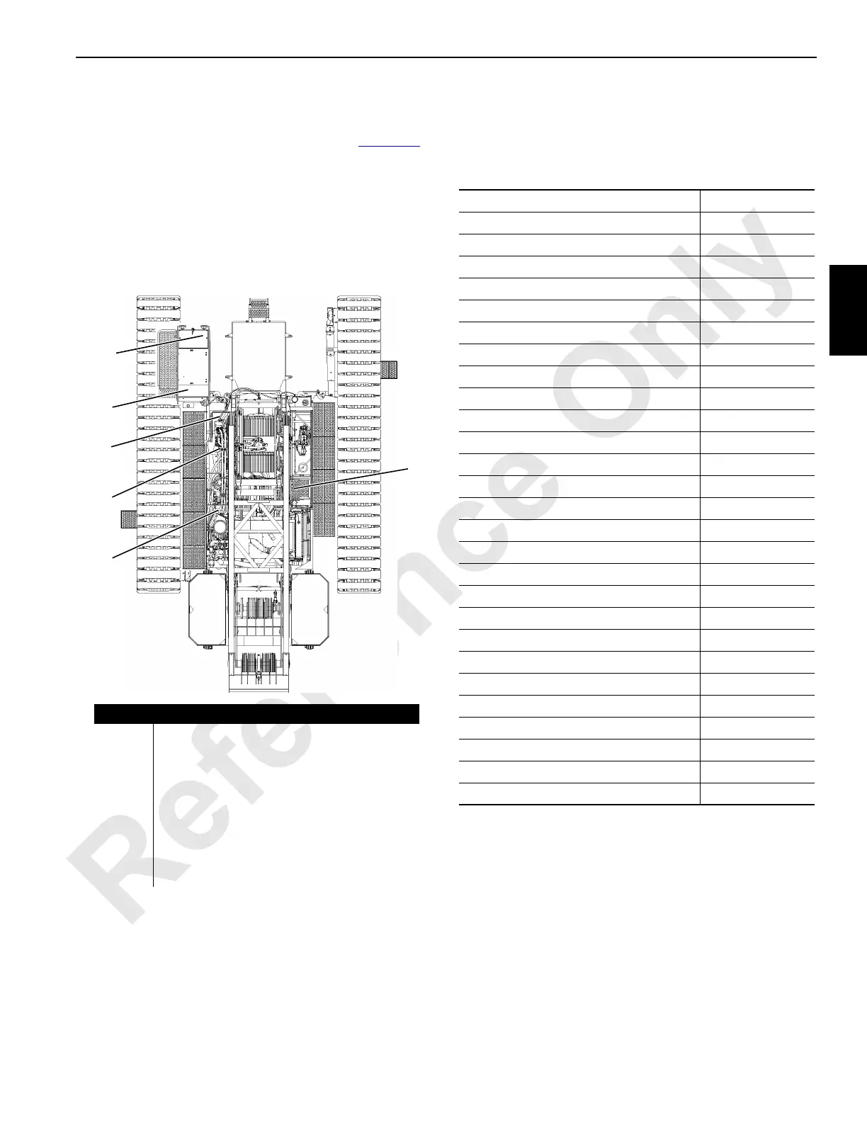
TEST VOLTAGES
On the following pages are Tables with test voltages sorted
by nodes. The nodes are listed and identified in Figure 3-2
.
The Model 14000 operating system is an EPIC
®
with CAN
Bus
®
technology. The CAN Bus system uses multiple nodes
that contain controllers. The controllers communicate with
node 1 (master) controller by sending data packets over a
two-wire bus line. The data packets are tagged with
addresses that identify system components of each node.
Component—Node Cross-Reference
This list may be useful when using the following Tables.
Check the component item node location, then refer to
indicated node to find the test voltage for that item.
Node Description
1 Master (Front Console)
2 Handles and Cab Controls
3
Drum 1, 2, and 3, Alarms, Sensors,
Accessories and Free Fall
4 Drum 4, Pumps, and Accessories
5 Swing Limit and Temperature Sensor
0 Engine and Circuit Breakers
RIN
(Boom)
Mounted on Boom – Block-Up, Angle Indicator,
Wind Speed, and Load Sensor.
FIGURE 3-2
14COM5-2
1
2
3
0
4
5
Component Location
Accessory System Components Node 3
Alarms Nodes1, 3 & 4
Air Conditioning Clutch Node 1
Auto Lube Pumps Node 4
Block Up Limit (Boom) Boom Node
Block Up Limit (Luffing Jib) Luffing Jib Node
Cab Switches and Controls Nodes 1 & 2
Cab Power Node 0
Cab Tilt Node 3
Control Handles Nodes 1 & 2
Boom Hoist (Drum 4) Components Nodes 3 & 4
Engine Control Module Node 0
Engine Fuel Level Sensor Node 3
Filters Nodes 4
Free Fall Components Node 3
Hydraulic Fluid Level and Temperature Node 4
Hydraulic Vacuum Switch Node 4
Limits Nodes 3 & 4
Front Drum Components Nodes 3
Rear Drum Components Nodes 3 & 4
Auxiliary/Luffing (Drum 3) Components Node 3
Pressure Senders Nodes 3 & 4
Swing Components Nodes 3 & 4
Throttle (Hand and Foot) Node 2
Travel Components Nodes 4
Wind Speed Indicator (Boom) Boom Node
Wind Speed Indicator (Luffing Jib) Luffing Jib Node
 Loading...


