INTRODUCTION 14000 SERVICE MANUAL
1-72
Published 09-05-14, Control # 226-02
Hydraulic Engine Cooling Fan
See Figures 1-40 and 1-41
The variable-speed cooling fan is powered by a hydraulic
motor. An engine-mounted pump supplies the flow to run the
fan motor. As engine load increases, the fan speed will also
increase to meet the cooling requirements of the engine.
NOTE: If there is an electrical failure, the fan will default to
high-speed operation.
A variable-speed fan provides several benefits including
quieter operation, higher efficiency and longer fan life. This
type fan also provides a more uniform engine temperature
and increased engine horsepower.
See the engine manufacturer’s operating instructions
manual for diagnostic information.
Fan speed is determined by the greatest demand of four
inputs: coolant temperature, air intake temperature (IMT),
hydraulic oil temperature and the state of the air conditioning
clutch. The system monitors these inputs every ten seconds
and adjusts the fan speed depending on the input readings.
A minimum fan speed indicator is included on the Main
display in the cab. The minimum fan speed can be adjusted
but this adjustment should be made only by the
manufacturer. It should not be changed by either the
operator or a service person.
Fan speed should never be 100%. If the actual fan speed
approaches 100%, the operator and/or service person
should investigate to determine the cause of the problem.
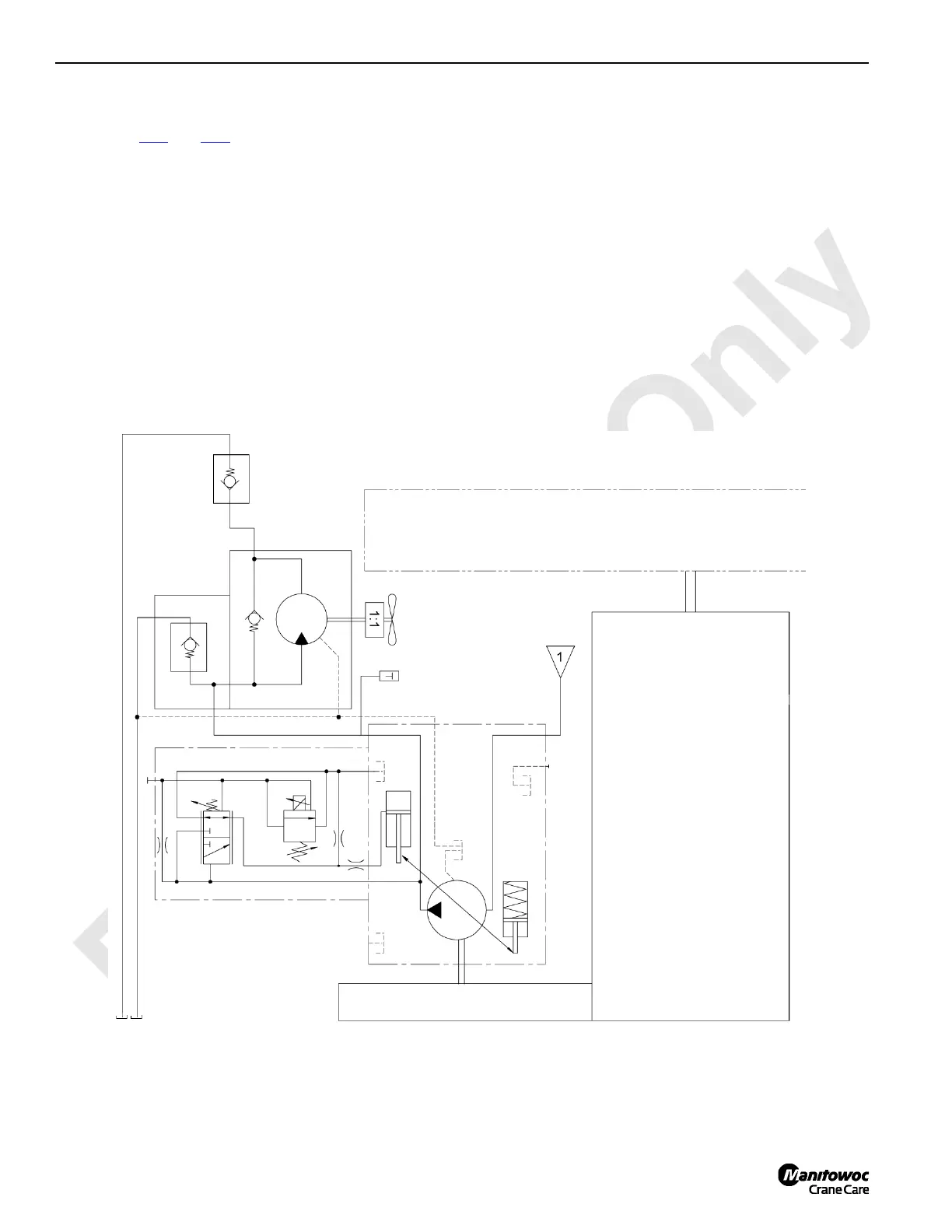
FIGURE 1-40
Return to
Reservoir
Suction
25 psi
(1.7 bar)
Check Valve
Fan Motor
3 psi
(0.2 bar)
7 psi
(0.3 bar)
Pump Drive Gearbox
Engine
Engine Driven Pump
 Loading...


