BOOM 14000 SERVICE MANUAL
4-2
Published 09-05-14, Control # 226-02
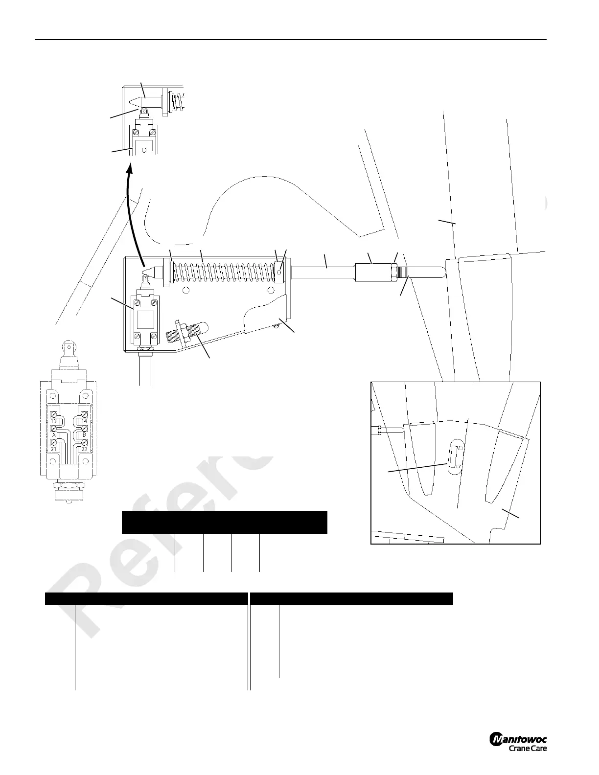
FIGURE 4-2
View A
Switch Opened
Item Description Item Description
1 Boom Butt 7 Cover
2a 84° Adjusting Rod – 5-1/4 in (133 mm) Long 8 Spring Washer
2b 88.5° Adjusting Rod – 3-1/2 in (88 mm) Long 9 Spring
3 Digital Protractor-Level 10 Spring Washer
4 Jam Nut 11 Dowel Pin 1/4 in (6 mm) Diameter
5 Coupling 12 Actuator Rod
6 Limit Switch
View C
Right Outboard Leg
Roller
Over-Travel
8 9 10 11
12
5
2a or 2b
4
1
2a or 2b
Stored
6
6
7
View B
Switch Closed
12
14CSM4-2
14CSM4-2c
14CSM4-2b
14CSM4-2ab
Limit Switch Wiring
Wire
Switch
Terminals
Function
1 (green) 22 14 Max Angle
2 (black) 13 GND
3 (white) 21 24 VDC Supply
 Loading...


