ELECTRIC SYSTEM 999 SERVICE/MAINTENANCE MANUAL
3-20
Published 05-16-17, Control # 233-03
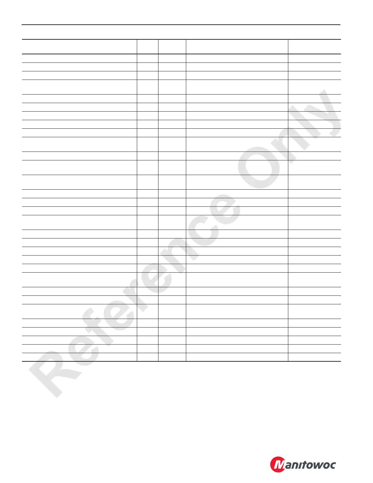
Rear Drum Park Brake Switch D-09 89X3 12 Volts Nominal I/O 3 J10-16 (DI)
Rear Drum Pawl Disable Solenoid D-35 81RA 12 Volts Nominal I/O 3 J10-39-40 (DO)
Rear Drum Pawl Enable Solenoid D-34 81R 12 Volts Nominal I/O 3 J10-37-38 (DO)
Rear Drum Pump Control (Servo Driver 2) C-06 81A
0 to 2.8 ± 10% (110 mA) Volts Down;
0 to -2. 8 ± 10% (-110 mA) Volts Up
I/O 1 J6-42 (AO)
Rear Drum Rotation Indicator D-28 81N 12 Volts Nominal I/O 3 J10-25-26 (DO)
Rear Drum Spring Clutch Solenoid C-29 81FS 12 Volts Nominal I/O 2 J8-29-30 (DO)
Remote Input Node Communication A-10 101 I/O 1 J5-64 (AI)
Remote Output Node Communication C-11 38 I/O 1 J6-29-30 (DO)
Remote Output Node Feedback B-13 39 I/O 1 J6-19 (DI)
Right Track Handle A-06 83P
0 Volts Neutral; 1.4 to 5 Volts Reverse;
5 to 8.6 Volts Forward
I/O 1 J5-56 (AI)
Right Track Hydraulic Pressure A-20 83Q 1.2 Volts at 300 psi; 1 Volt at 0 psi CPU J3-49 (AI)
Right Track Pedal A-12 83PF
0 Volts Neutral; 1.4 to 5 Volts Reverse;
5 to 8.6 Volts Forward
I/O 2 J7-50 (AI)
Right Track Pump Control (Servo Driver 4) C-15 83A
0 to 2.8 ± 10% (110 mA) Volts Reverse;
0 to -2. 8 ± 10% (-110 mA) Volts Forward
I/O 2 J8-42 (AO)
Rotating Bed Auto-Lube Relay E-33 80G 12 Volts Nominal I/O 4 J12-25-26 (DO)
RS232 - Receive from Laptop D-16 37 CPU J4-02 (COMM)
RS232 - Receive from LMI D-21 35 CPU J4-10 (COMM)
RS232 - To Display – Black (Ground) D-20 30 0 Volts
CPU J4-07-08
(COMM)
RS232 - To Display - White D-19 31 CPU J4-05 (COMM)
RS232 - Transmit to Laptop D-17 36 CPU J4-01 (COMM)
RS232 - Transmit to LMI D-22 34 CPU J4-09 (COMM)
Seat Switch B-34 89Q3 12 Volts Nominal I/O 3 J10-12 (DI)
Swing Auto-Lube Relay E-34 85G 12 Volts Nominal I/O 4 J12-27-28 (DO)
Swing Handle A-08 85P
0 Volts Neutral; 1.7 to 5 Volts Right;
5 to 8.3 Volts Left
I/O 1 J5-60 (AI)
Swing Left Hydraulic Pressure A-26 85QL 1.2 Volts at 300 psi; 1 Volt at 0 psi CPU J3-61 (AI)
Swing Park Brake Switch D-15 85EA 12 Volts Nominal I/O 4 J12-08 (DI)
Swing Pump Control (Servo Driver 6) C-24 85A
0 to 2.8 ± 10% (110 mA) Volts Right;
0 to -2. 8 ± 10% (-110 mA) Volts Left
I/O 3 J10-42 (AO)
Swing Right Hydraulic Pressure A-25 85QR 1.2 Volts at 300 psi; 1 Volt at 0 psi CPU J3-59 (AI)
Tracks Auto-Lube Relay E-35 84G 12 Volts Nominal I/O 4 J12-29 30 (DO)
Travel Detent B-01 89X 12 Volts Nominal I/O 1 J6-07 (DI)
Travel Park Brake Solenoid C-10 84E 12 Volts Nominal I/O 1 J6-27-28 (DO)
Travel Park Brake Switch D-11 89B4 12 Volts Nominal I/O 3 J10-18 (DI)
Description Pin Wire
Test Voltage
(DC unless otherwise specified)
Board
(Signal Type)

 Loading...


