Manitowoc Published 05-16-17, Control # 233-03 10-37
999 SERVICE/MAINTENANCE MANUAL TROUBLESHOOTING
Test 5 – Continued
The above test adapters can be ordered from the Manitowoc
Crane Care Lattice Team. The pressure sender, encoder,
EDC/PCP, and hydraulic/brake valve adapters are for testing
various components as described in this manual.
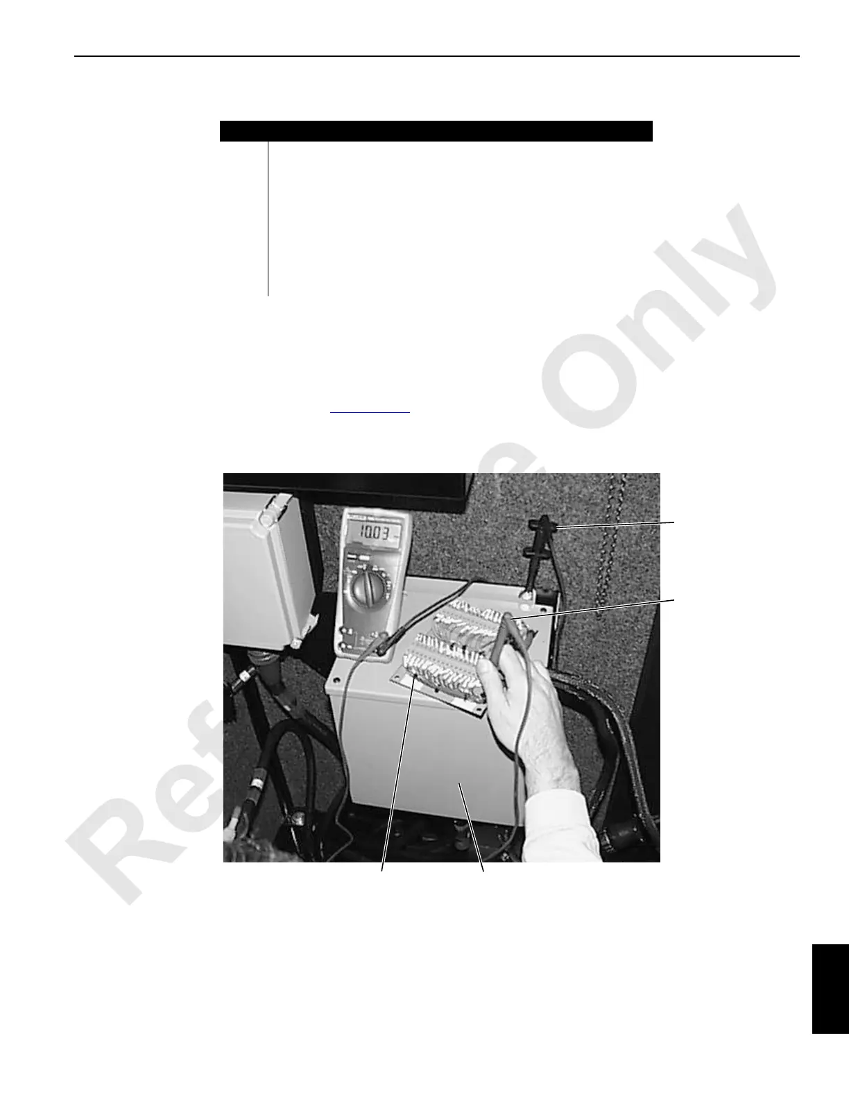
To test a problem circuit, insert male or female in-line testing
board (5) at CPU (6) cable connector. See Test Voltages
in
Section 3 of this manual for circuit wires located on each
cable connector A, B, C, D and E with pins numbered 1
through 37. Connect meter negative lead (7) to ground and
positive lead (8) to problem item terminal. Check for
12 volts DC (10 volts DC for regulated supply items as
shown) at problem circuit wire terminal on in-line testing
board.
Item
Description
1 Hydraulic/Brake Valve Adapter Cable (P/N 1776422)
2 Pressure Sender Adapter Cable (P/N 1776412)
3 EDC/PCP Adapter Cable (P/N 1776442)
4 Encoder Adapter Cable (P/N 1776432)
5 In-line Testing Boards Set — Male and Female Pins (P/N 417350)
6CPU
7 Negative Lead Ground (black)
8 Positive Lead (red)

 Loading...


