Manitowoc Published 05-16-17, Control # 233-03 1-17
999 SERVICE/MAINTENANCE MANUAL INTRODUCTION
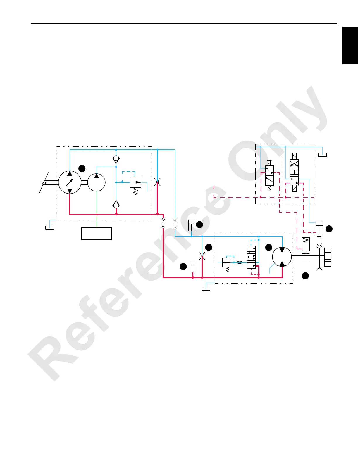
When swing handle is moved to right, an input voltage of 5
volts or less is sent to the PC. The PC sends a positive
output voltage to swing pump EDC. Swing pump swashplate
tilts relative to swing handle movement. Fluid flows from
swing pump port A to swing motor port A, moving rotating
bed to the right.
As swing handle is moved to neutral position, the PC sends
an output signal to adjust swashplate to centered position.
When in a swinging motion, the preferred way to stop or slow
crane is to move swing handle beyond center in the opposite
direction. This allows rotating bed to gradually stop.
Swing Holding Brake Switch
Swing holding brake switch (10) on side of swing handle,
holds rotating bed in position (applies swing park brake) for
short periods when operating. To prevent damage to swing
system, swing holding brake switch must only be applied
when crane is at a standstill.
When swing holding brake switch is pressed in and held,
circuit to swing brake release solenoid HS-8 is opened,
allowing fluid to exhaust to tank and brake spring-applies.
Crane rotating bed is stopped while switch is held. When
swing holding brake switch is released, circuit to swing brake
release solenoid HS-8 is closed, allowing charge pressure to
hydraulically release spring-applied park brake.
FIGURE 1-10
SWING PUMP
A
B
350 PSI
(24 BAR)
SWING
SUCTION
MANIFOLD
CHARGE
PUMP
LOCK
SWING LEFT
SWING RIGHT
.060
X
X
HS-10
HS-9
HS-8
PILOT CHARGE PRESSURE
FROM REAR DRUM PUMP
BRAKE
SWING
200 PSI
(14 BAR)
B
A
.060
999CSM1-109
3
5
3
6
3
7
3
6
3
9
3
3
3
2

 Loading...


