TROUBLESHOOTING 999 SERVICE/MAINTENANCE MANUAL
10-44
Published 05-16-17, Control # 233-03
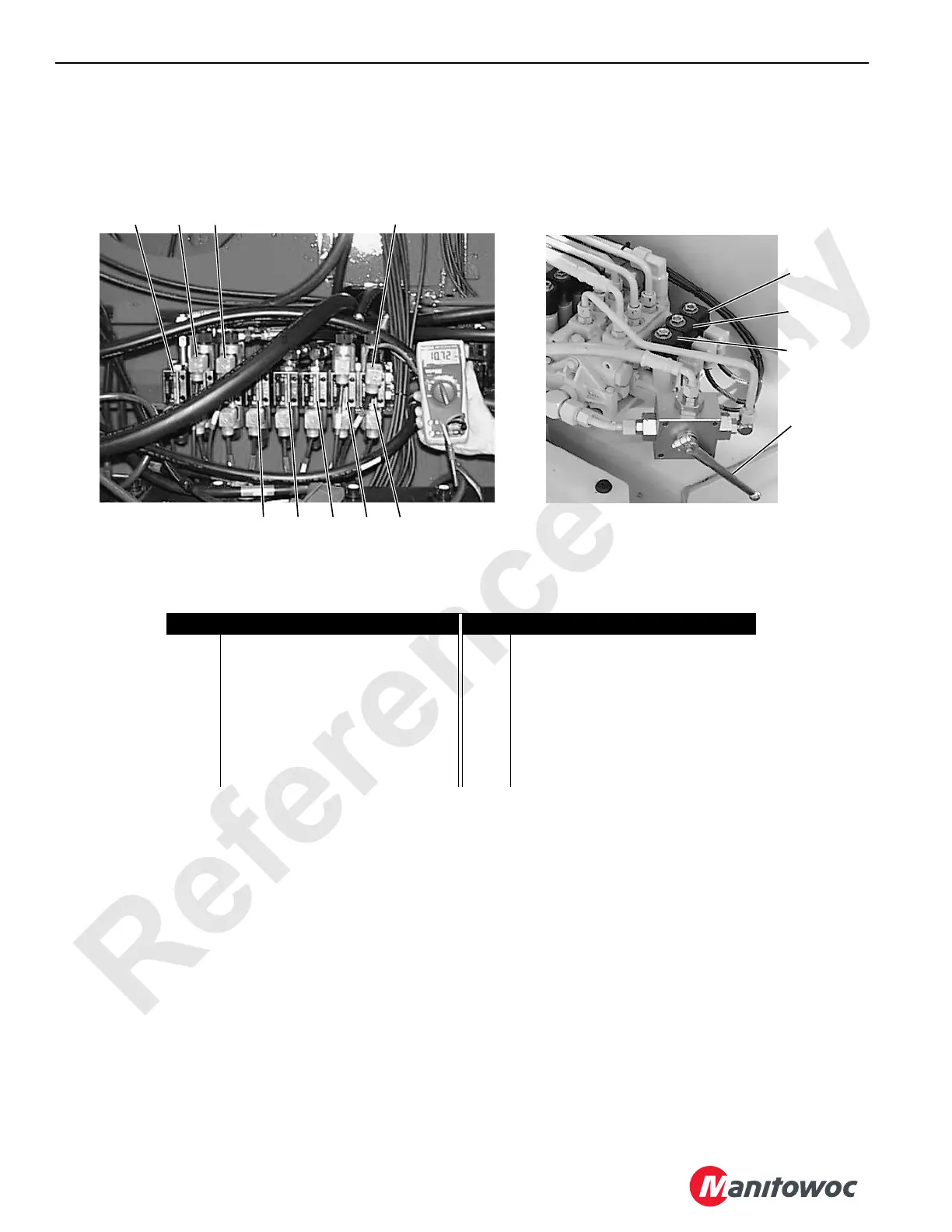
Test 12 – Checking Voltage at the Hydraulic Valve Assemblies
To determine if a hydraulic solenoid is enabled, place a
screwdriver on the solenoid coil. The solenoid is enabled if
screwdriver is magnetically pulled toward the solenoid coil.
Measure system voltage at various locations with a standard
test adapter (can be ordered from the Manitowoc Crane
Care Lattice Team) and a digital multi-meter.
To test a hydraulic valve:
• Set digital multi-meter for testing volts DC.
• Connect white (positive) and black (negative) wires from
adapter cable to digital multi-meter jacks.
• Install test adapter between solenoid valve electrical
socket and DIN plug.
• Enable valve under test.
• Check for 12 volts DC at upper valve assembly.
Item
Description
Item
Description
1 Counterweight Pin Solenoid Valve 8 Front Drum Pawl Solenoid Valve
2 Boom Hoist Pawl Solenoid Valve 9 Mast Arms Bypass Valve
3 Swing Lock Solenoid Valve 10 Mast Assist Cylinders Solenoid Valve
4 Swing Brake Solenoid Valve 11 Gantry Cylinders Solenoid Valve
5 Two-Speed Travel Solenoid Valve 12 Boom Hinge Pins Solenoid Valve
6 Travel Brake Solenoid Valve 13 Hydraulic/Brake Valve Adapter Cable
7 Rear Drum Pawl Solenoid Valve
12
P1493P1596
11
10
9
87654
1 2 3 13
In Right Side Enclosure

 Loading...


