Manitowoc Published 05-16-17, Control # 233-03 10-41
999 SERVICE/MAINTENANCE MANUAL TROUBLESHOOTING
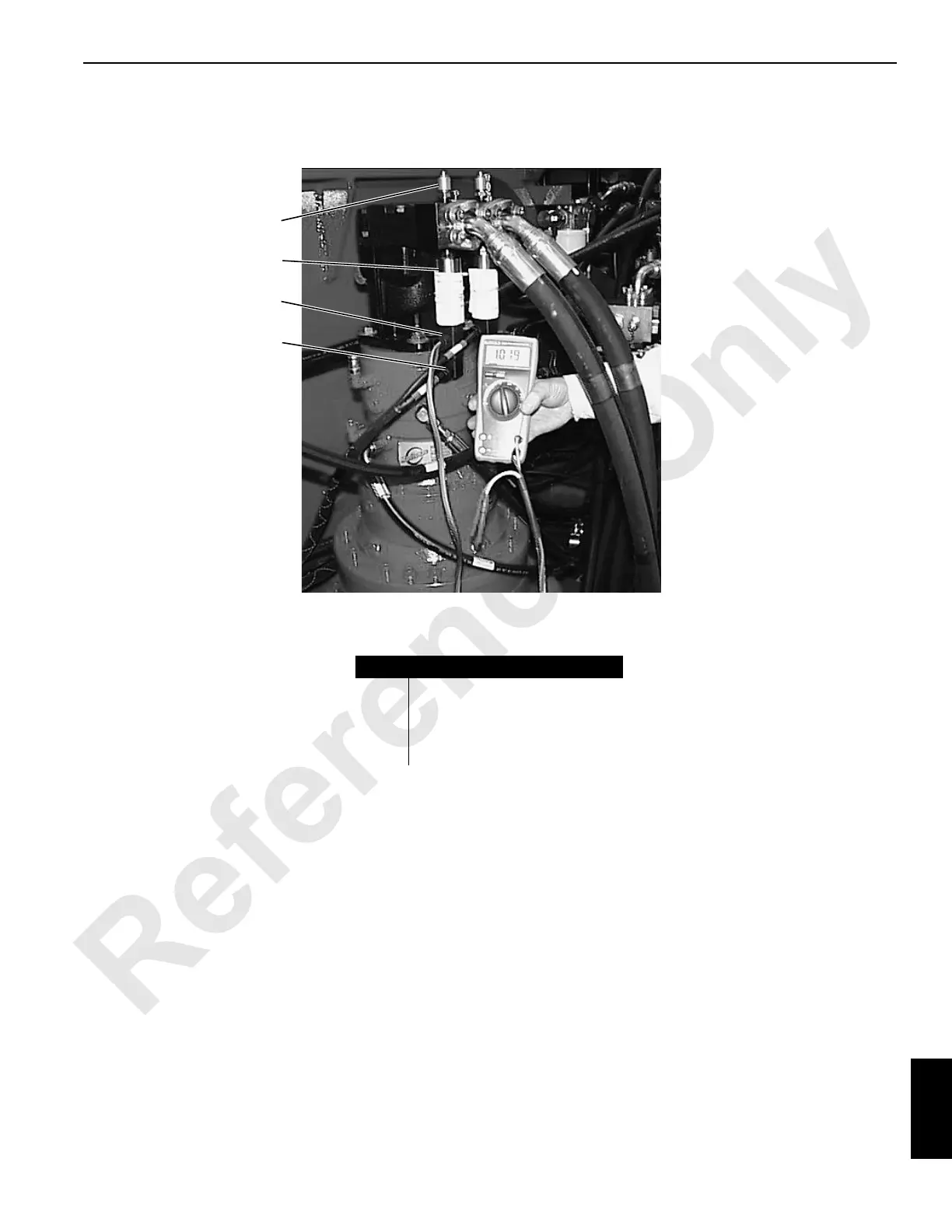
Test 9 – Checking Voltage at the Pressure Senders
Test voltage and resistance of a system pressure sender with
a standard test adapter (can be ordered from the Manitowoc
Crane Care Lattice Team) and a digital multi-meter.
To test incoming power at desired pressure sender:
• Connect test adapter between pressure sender and DIN
plug.
• Connect white (positive) and black (negative) wires from
adapter cable to digital multi-meter jacks.
• Check for 12 volts DC.
• If this reading is not obtained, check for 5 amps at F8
fuse on fuse panel (see Test 6).
To test voltage output from the pressure sender to the PC:
• Engine must be off and power on, with all brakes and
locks engaged.
• Connect green (positive) and black (negative) wires to
digital multi-meter jacks.
• Check for 1.00 to 1.04 volts DC.
The PC null or zero routine permits the pressure sender to
operate outside the above voltage range. If reading is 0.80
volts or less or 1.20 volts or more, pressure sender must be
replaced.
Item
Description
1 System Pressure Test Port
2 Pressure Sender
3 Pressure Sender Test Adapter
4 DIN Connector

 Loading...


