Manitowoc Published 05-16-17, Control # 233-03 7-11
999 SERVICE/MAINTENANCE MANUAL POWER TRAIN
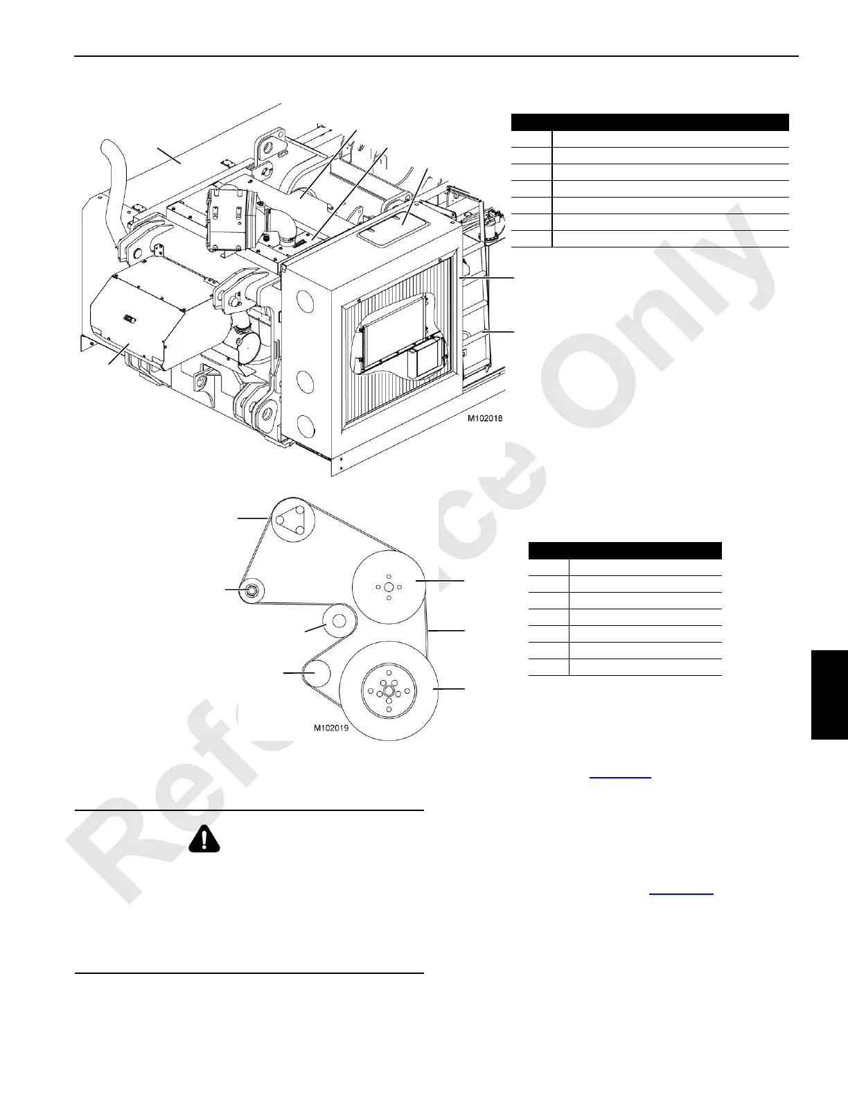
ENGINE ENCLOSURE
The engine enclosure (Figure 7-8) has panels that can be
removed to allow access to the engine for servicing.
Do not operate the crane until all enclosures have been
securely reinstalled.
ENGINE BELT ROUTING
Engine belt routing is shown in Figure 7-9. Refer to the
engine manufacturer’s manual for maintenance instructions.
FIGURE 7-8
Item Description
1 Ladder
2 Radiator Enclosure
3 Radiator Access Door with Latches
4 Engine Covers (3) (with quarter-turn latches)
5 Engine Cover (with screws)
6 Exhaust System Enclosure
7 Left-Side Enclosure
Right-Rear Corner of Crane
1
2
5
4
3
Enclosure Door Not
Shown for Clarity
6
7
FIGURE 7-9
Looking at Engine
from Fan End
Item Description
1Belt
2 Crankshaft Pulley
3 Belt Tensioner
4 Water Pump
5 Alternator
6 Air Conditioner Compressor
7 Idler Pulley
2
3
5
6
4
1
7
WARNING
Fall Hazard
It is necessary to climb onto the engine enclosure to
inspect and service the air cleaner and engine.
Use the access ladder on the right side of the upperworks
to climb onto the engine enclosure.
Take every precaution to prevent falling off the crane.

 Loading...


