Manitowoc Published 05-16-17, Control # 233-03 2-13
999 SERVICE/MAINTENANCE MANUAL HYDRAULIC SYSTEM
a. If 0 appears, all items have passed.
b. If any number other then 0 appears, use Table 2-10.
to determine which items have failed.
NOTE: The cause of a failed calibration or faulty display
pressure reading in the cab may not be the
pressure sender. The cause of the fault could be
trapped air or hydraulic pressure in the system.
Before replacing a pressure sender, do the
following:
• Perform pressure sender calibration steps.
• Attach an accurate hydraulic pressure gauge
to the quick-coupler at the suspect pressure
transducer.
• If pressure appears on the gauge, bleed the
corresponding system so the gauge reads
zero pressure.
• Repeat calibration steps and check pressure
on the display in the cab with the engine
running at idle — the display reading and the
gauge reading should be the same.
• Before replacing a pressure sender, check the
signal voltage at the sender. It should be 1.0
volt against group at 0 psi.
Charge Pressure
The charge pressure screen (Figure 2-10) indicates if each
system’s charge pressure is within 275 – 400 psi (19 – 27
bar), as monitored by the computer.
Charge pressure should be checked at the following
intervals:
• When a new programmable controller is installed
• When a new CPU board is installed
• When a new controller chip is installed
• When a pump is replaced
• When a pump control (EDC or PCP) is replaced
• Every 6 months
To check charge pressure, proceed as follows:
1. Start engine and run at low idle.
2. Access calibration screen (see Accessing Calibration
Screens).
3. Screen indicates state of charge pressure:
a. If 0 appears, charge pressure is okay for all items.
b. If any number other then 0 appears, use Table 2-10.
to determine which items are not within specified
charge pressure.
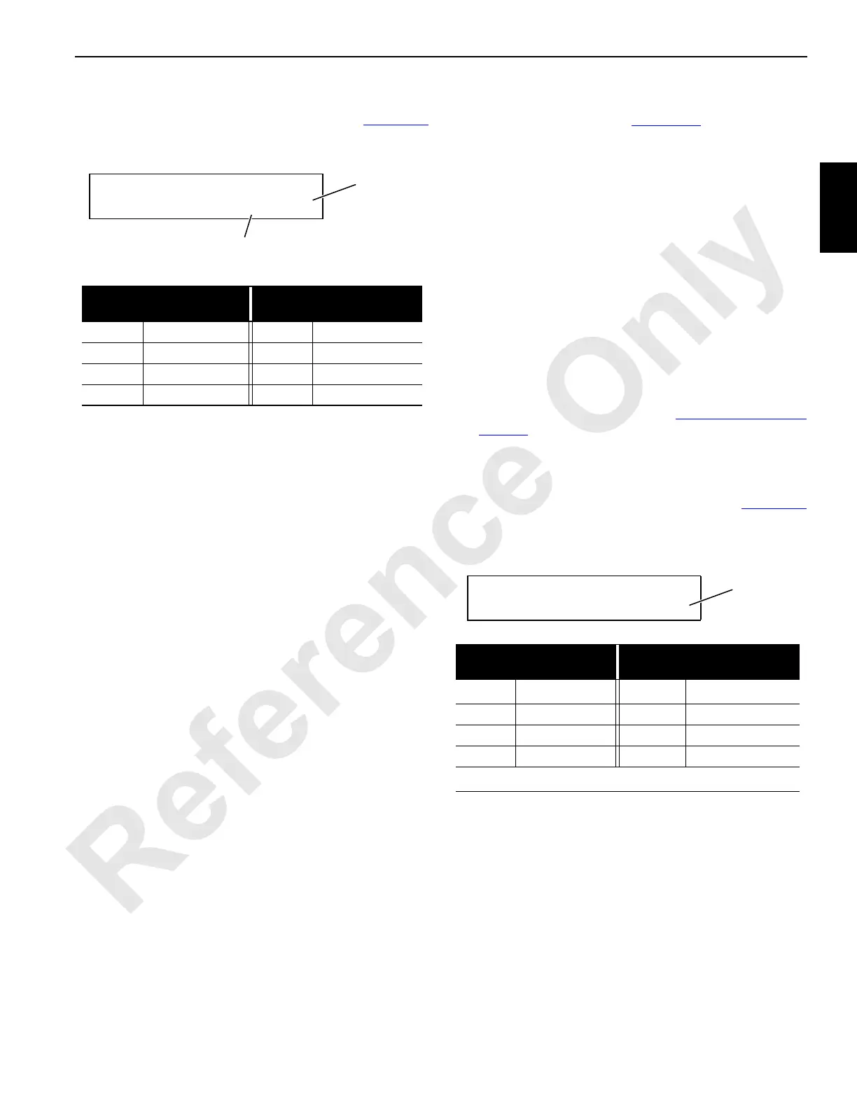
HYD SYSTEM CHECK
* PRES SENDER 0% 15
FIGURE 2-9
Binary
Number
Percent
Complete
Binary
Number
Calibration Item
Binary
Number
Calibration Item
1 Front Drum 16 Swing Left
2 Rear Drum 32 Travel Right
4 Boom Hoist 64 Travel Left
8 Swing Right 128 Accessory System
HYD SYSTEM CHECK
* CHARGE PRES 15
FIGURE 2-10
Binary
Number
Binary
Number
Calibration Item
Binary
Number
Calibration Item
1 Front Drum 16
Swing Left
1
2 Rear Drum 32 Travel Right
4 Boom Hoist 64 Travel Left
8 Swing Right 128 Accessory System
1
Same Pump as Swing Right

 Loading...


