Manitowoc Published 05-16-17, Control # 233-03 3-33
999 SERVICE/MAINTENANCE MANUAL ELECTRIC SYSTEM
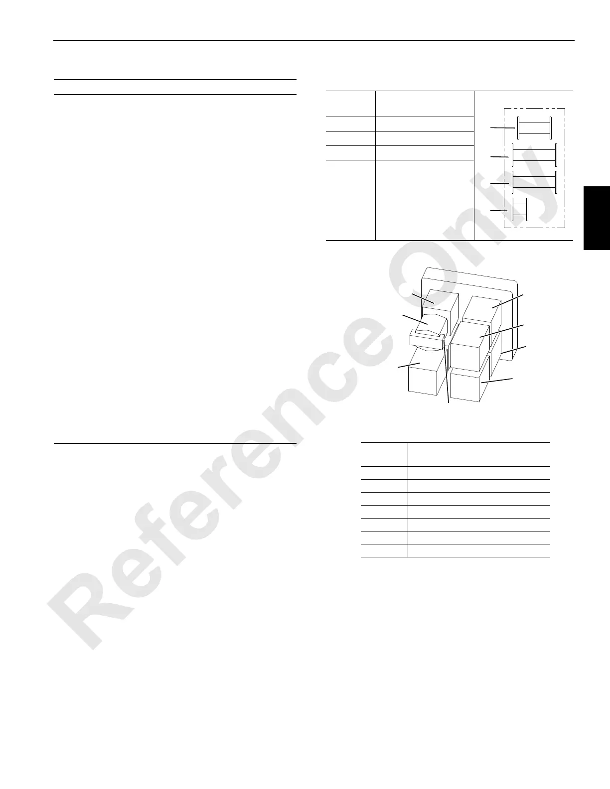
Table 3-5 Display Abbreviations Table 3-6 Drum and Pump Identification
Abbreviation Definition
+
–
%
A1
A2
A3
ANG
AUX
CALIB
CHRG
CON
D1
D2
D3
DEG
DEG F
FWD
FFall
HYD
LUFF
MIN
MAX
PRESS
PSI
PSIA
RPM
RIN
SEND
SYS
TEMP
Plus
Minus
Percent
Handle Inputs
Pump Control Outputs
Programmer’s Screen
Angle
Auxiliary
Calibration
Charge
Configuration
Digital On-Off Inputs
Digital Inputs
Digital Inputs or Outputs
Degrees (angle)
Degrees Fahrenheit
Forward
Free Fall
Hydraulic
Luffing
Minimum
Maximum
Pressure
Pounds Per Square Inch
Pounds Per Square Inch Absolute
Revolution Per Minute
Remote Input Node
Sender
System
Temperature
Pump Identification
Pump
Number Crane
0 Front Load Drum
1 Rear Load Drum or Luffing Hoist
2Boom Hoist
3 Swing
4 Right Crawler
5 Left Crawler
10 Auxiliary Load Drum (in butt)
CRANE
A817
Super Charge
Pump
2
1
3
10
5
0
4
Drum
Number
Drum
1 Front Load Drum
2 Rear Load Drum
4 Boom Hoist
8
Auxiliary Load Drum
(in boom butt)

 Loading...


