INTRODUCTION 999 SERVICE/MAINTENANCE MANUAL
1-46
Published 05-16-17, Control # 233-03
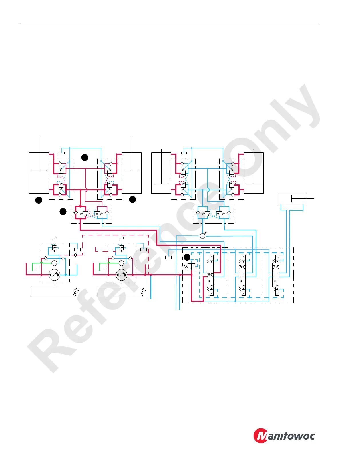
The PC sends a negative output voltage to rear drum pump
EDC (13) that tilts rear drum pump swashplate to stroke
pump in the low-pressure side direction. Low-pressure side
hydraulic fluid flows to gantry extend cylinder solenoid HS-3
of upperworks accessory valve and through free flow check
valve sections on side “A” of load equalizing valve (8). From
the equalizing valve, fluid enters counterbalance valves (7)
and piston end of gantry cylinders (6), extending cylinder
rods to raise the gantry. As gantry raises, boom hoist drum
pays out wire rope.
The PC monitors rear drum pressure senders to control
gantry cylinder raising speed rate.
The free-flow check valve sections on side “B” of
counterbalance valves block fluid exhausting from rod end of
gantry cylinders. Fluid passes through flow restrain sections
of counterbalance valve that have a relief setting of 3,500 psi
(240 bar). Counterbalance valves act as a deceleration
control and operate with a 5:1 pilot ratio of the relief valve
pressure, permitting the valves to open when pressure in the
piston end of cylinders is approximately 700 psi (48 bar).
Exhaust fluid from side “B” of both counterbalance valves
combines and fluid passes through non-restrictive portion of
load equalizing valve before entering accessory system
valve. Hydraulic fluid exits the accessory system valve and
returns to tank.
The free-flow check valve sections on side “B” of load
equalizing valve block the flow. Hydraulic fluid then passes
through flow restrain section of valve that is preset at 4,000
psi (275 bar).
Load equalizing valve operates with a 1.5:1 pilot ratio of the
relief valve pressure, permitting valve to open when
hydraulic pressure from the setup pump (rear drum) on side
“A” of the valve is approximately 2,670 psi (185 bar).
Restraining section on side “B” of load equalizing valve
opens, controlling fluid out of both cylinders and ensuring
cylinder actuation is balanced.
When gantry is fully raised, gantry up limit switch closes
sending an input signal to PC. The PC sends an output
signal to de-stroke rear drum pump. The PC also sends an
output signal to shift gantry extend cylinder solenoid HS-3
back to center position. The PC goes to next sequence step
of raising mast.
FIGURE 1-33
HIGH
UPPERWORKS ACCESSORY MANIFOLD
REAR DRUM
PUMP DRIVE GEARBOX
HS-4
A
A
A
BB
B
BOOM HINGE
PIN
CYLINDER
LOAD EQUALIZING
VALVE
4,000 PSI (275 BAR)
MAST RAISING CYLINDERS
3,500 PSI (240 BAR)
LOW
HS-3
HS-2
HS-1
HS-6
HS-5
3
7
A
A
A
BB
B
LOAD EQUALIZING
VALVE
4,000 PSI (275 BAR)
GANTRY CYLINDERS
3,500 PSI (240 BAR)
HIGH
FRONT DRUM
PUMP DRIVE GEARBOX
LOW
LOW PRESSURE
ACCESSORIES
3
8
3
6
TO LOWERWORKS
ACCESSORY MANIFOLD
3
6
999CSM1-132
TO REAR HOIST MOTOR
LOOP FLUSHUNG VALVE
3
14

 Loading...


