Manitowoc Published 05-16-17, Control # 233-03 1-49
999 SERVICE/MAINTENANCE MANUAL INTRODUCTION
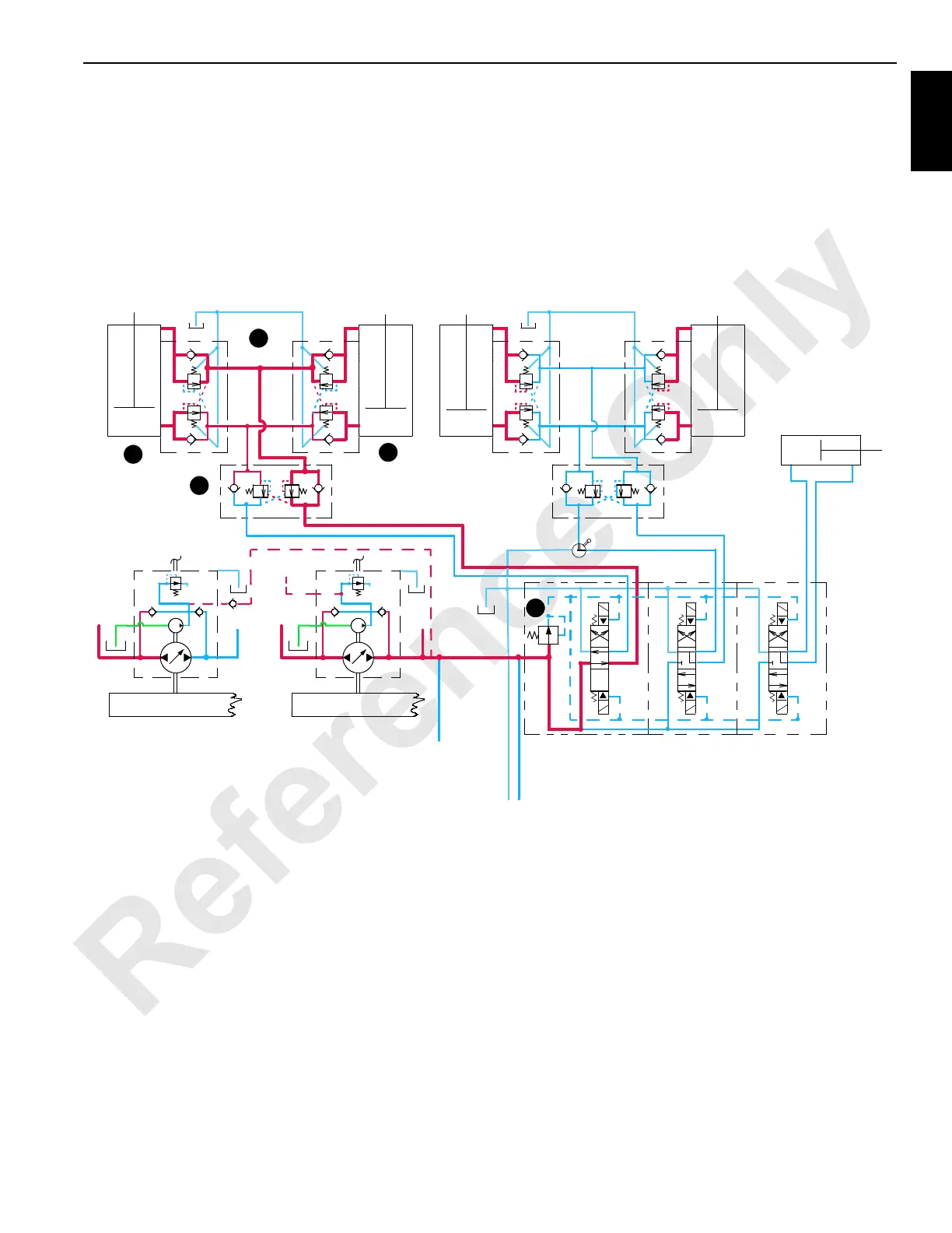
equalizing valves is approximately 2,670 psi (185 bar).
Restraining section on side “A” of load equalizing valve
opens, controlling fluid out of both cylinders and ensuring
cylinder actuation is balanced. Hydraulic fluid exits the
accessory system valve through gantry valve section and
returns to tank.
When gantry is fully lowered, boom hoist handle is moved to
neutral position to stop hauling in wire rope to drum. After
control handle neutral switch opens, the PC sends an output
signal to disable brake release solenoid HS-13 to spring-
apply brake before hoist pump de-strokes.
The PC sends an output signal to de-stroke rear drum pump
and boom hoist pump. The PC also sends an output signal to
shift gantry lower cylinder solenoid HS-4 back to center
position.
FIGURE 1-35
HIGH
UPPERWORKS ACCESSORY MANIFOLD
REAR DRUM
PUMP DRIVE GEARBOX
HS-4
A
A
A
BB
B
BOOM HINGE
PIN
CYLINDER
LOAD EQUALIZING
VALVE
4,000 PSI (275 BAR)
MAST RAISING CYLINDERS
3,500 PSI (240 BAR)
LOW
HS-3
HS-2
HS-1
HS-6
HS-5
3
7
A
A
A
BB
B
LOAD EQUALIZING
VALVE
4,000 PSI (275 BAR)
GANTRY CYLINDERS
3,500 PSI (240 BAR)
HIGH
FRONT DRUM
PUMP DRIVE GEARBOX
LOW
LOW PRESSURE
ACCESSORIES
3
8
3
6
TO LOWERWORKS
ACCESSORY MANIFOLD
3
6
999CSM1-134
TO REAR HOIST MOTOR
LOOP FLUSHING VALVE
3
14

 Loading...


