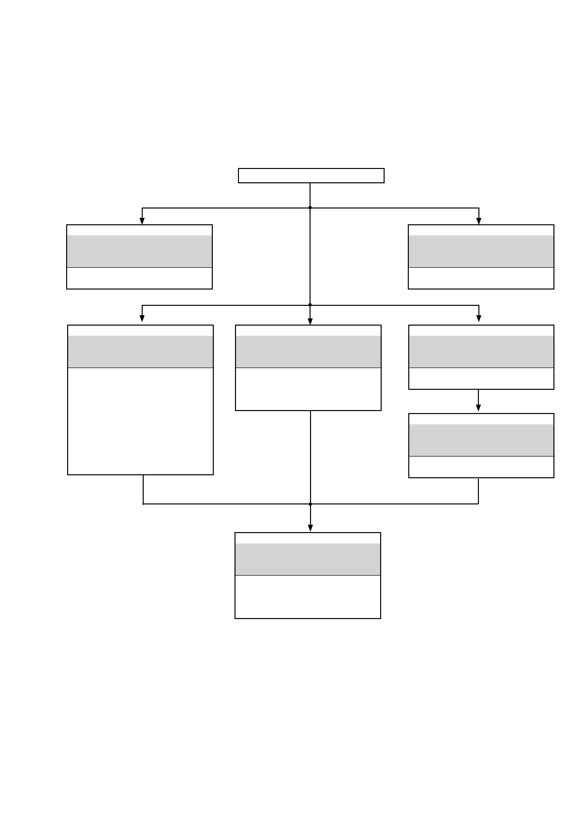
DISASSEMBLY
• Remove each part in the order of the arrows below.
• Reassemble removed parts in the reverse order.
• Read "Precautions During Work" before reassembling removed parts.
• If wire bundles are removed or moved during adjustment or part replacement, reshape the wires after completing the
work. Failure to shape the wires correctly may cause problems such as noise.
FRONT PANEL ASSY
See
"DISASSEMBLY
1. FRONT PANEL ASSY
and
"EXPLODED VIEW"
HEADPHONE PCB
(Ref. No. of EXPLODED VIEW : P8)
STANDBY LED PCB
(Ref. No. of EXPLODED VIEW : P5)
FRONT PCB
(Ref. No. of EXPLODED VIEW : P7)
SELECTER PCB
(Ref. No. of EXPLODED VIEW : P6)
POWER SW PCB
(Ref. No. of EXPLODED VIEW : P10)
TOP COVER
TRANS POWER
See
"DISASSEMBLY
7. TRANS POWER
and
"EXPLODED VIEW"
MAIN TRANS
(Ref. No. of EXPLODED VIEW : T0001)
HEAT SINK ASSY
See
"DISASSEMBLY
2. HEAT SINK ASSY
and
"EXPLODED VIEW"
POWER BUFFER PCB
(Ref. No. of EXPLODED VIEW : P2)
CLAMP PCB
(Ref. No. of EXPLODED VIEW : P9)
DIGITAL PCB
See
"DISASSEMBLY
3. DIGITAL PCB
and
"EXPLODED VIEW"
DIGITAL
PCB
(Ref. No. of EXPLODED VIEW : P4)
PHONO HDAM PCB
See
"DISASSEMBLY
4. PHONO HDAM PCB
and
"EXPLODED VIEW"
PHONO HDAM PCB
(Ref. No. of EXPLODED VIEW : P12)
MAIN PCB
See
"DISASSEMBLY
5. MAIN PCB
and
"EXPLODED VIEW"
MAIN PCB
(Ref. No. of EXPLODED VIEW :P1)
VOLUME PCB
(Ref. No. of EXPLODED VIEW : P14)
STANDBY PCB
See
"DISASSEMBLY
6. STANDBY PCB
and
"EXPLODED VIEW"
STANDBY PCB
(Ref. No. of EXPLODED VIEW : P11)
11