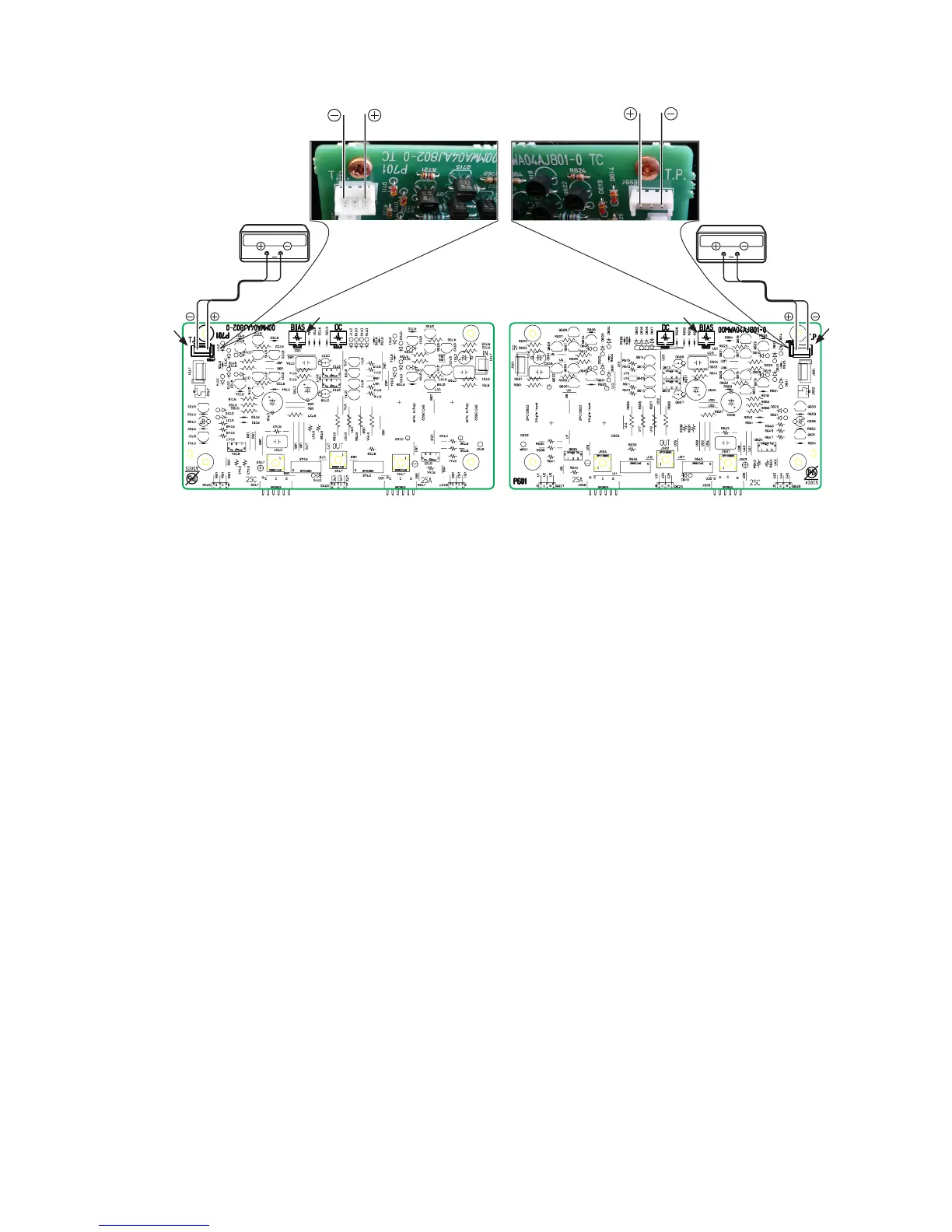
Idling Current Adjustment
1. After DC Offset Voltage Adjustment is completed, adjust
the Idling Current with the variable resistor R633 and
R733 on the PWB (P601/P701).
2. Turn off the power.
3. "+" of Connect Digital Voltage is connected to the No. 1
pin and connected "–" to No. 3 pin of J653.
4. "+" of Connect Digital Voltage is connected to the No. 1
pin and connected "–" to No. 3 pin of J753.
5. Before turning on the power, R633 and R733 have been
counter clockwise turned with the adjustment driver.
6. Turn on the power, VOLUME is set as -∞.
7. With seeing the digital voltage meter turn the variable
resister clockwise slowly to adjust the idling current.
• IdlingadjustmentwithR633 (R733).
• TurnR633 (R733) clockwise to increase the idling
current.
• Theadjustmentvalueofidlingcurrentis
"9.6 mV(48 mA) ± 0.5 mV(2.5 mA)" each.
8. After 5 minutes, repeat the same procedure as 7.
• TurnR633 (R733) clockwise to increase the idling
current.
• Theadjustmentvalueofidlingcurrentis
"10.4 mV(52 mA) ± 0.5 mV(2.5 mA)" each.
Adjustment is completed.
9. Remove connection cable, attach the top cover.
Idling current decreases with the temperature rise inside the
unit, and it is set to "10mV (50mA)" of setting value in about
30 minutes after turn on the power.
P701(R ch) P601(L ch)
R733
J653
R633
J753
アイドリング電流調整
1. DCオフセット電圧調整終了後、P601/P701基板上の半固定
抵抗R633とR733でアイドリング電流を調整します。
2. 電源をOFFします。
3. P601基板のJ653にデジタルボルトメーターを接続します。
デジタルボルトメーターはJ653の1番ピンを"+", 3番ピン
を"−"に接続します。
4. P701基板のJ753にデジタルボルトメーターを接続します。
デジタルボルトメーターはJ753の1番ピンを"+", 3番ピン
を"−"に接続します。
5. 電源を投入する前に半固定抵抗R633とR733を、調整ドラ
イバーで反時計方向に回しきってください。
6. 電源を投入しボリュームを-∞にしてください。
7. P601/P701基板のJ653/J753に接続したデジタルボルトメータ
ーの電圧値を監視しながら、半固定抵抗R633とR733をゆっく
りと時計向に回してください。
• R633と R733を時計方向に回すとアイドリング電流が増
加します。
• アイドリング電流の調整値はそれぞれ
"9.6 mV(48 mA) ± 0.5 mV(2.5 mA)"とします。
8. さらに"5分"経過後、上記7.の手順でもう一度調整します。
• アイドリング電流の調整値はそれぞれ
"10.4 mV(52 mA) ± 0.5 mV(2.5 mA)"とします。
以上で調整は完了です。
9. デジタルボルトメーターの接続を外し、トップカバーを取
付けます。
調整終了後トップカバーを取付けるとセット内部の温度上昇に
伴いアイドリング電流が減少し、電源投入後約30分で設定値
の"10mV(50mA)"になります。
 Loading...