2
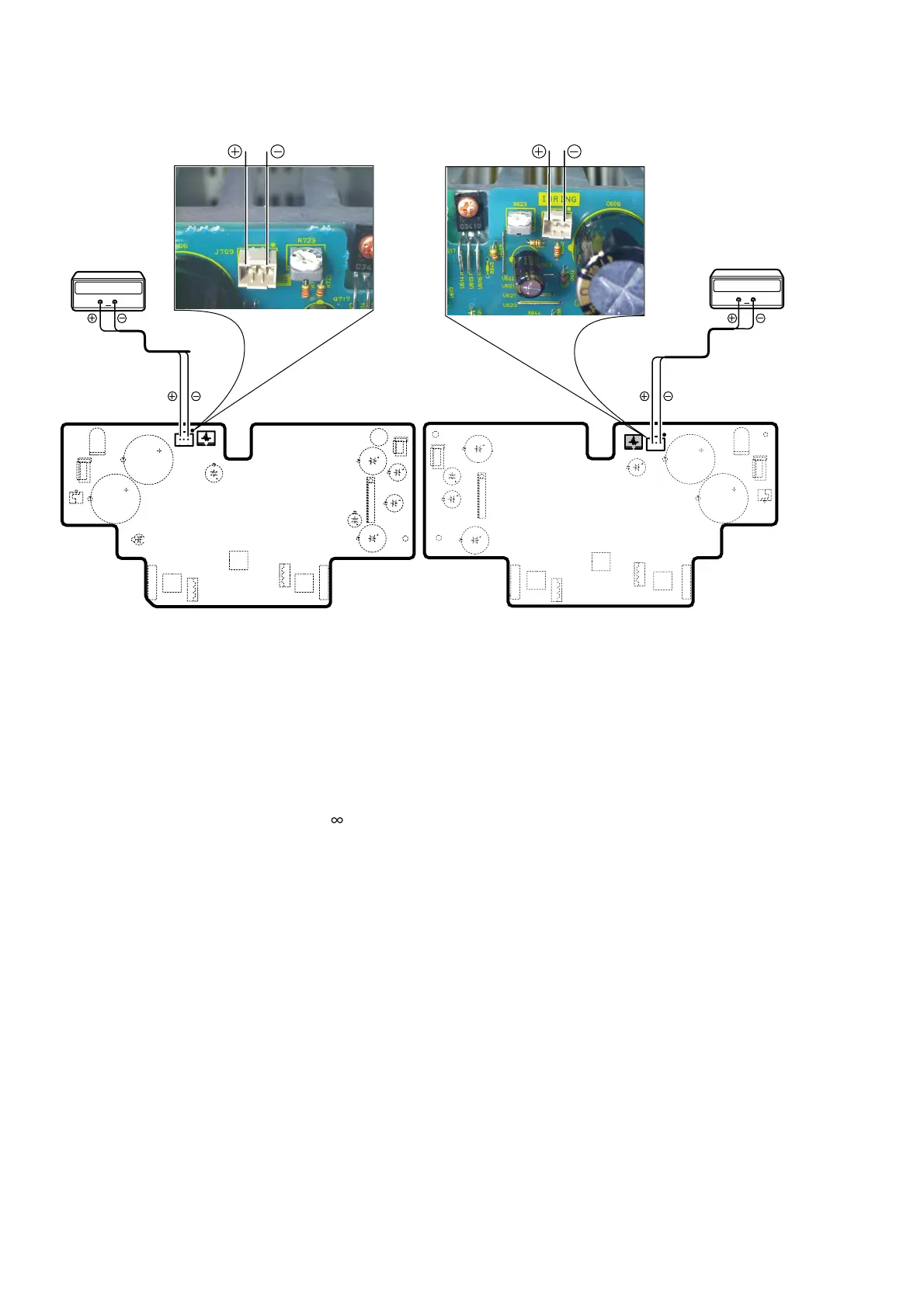
P701
P601
R723
J709
R623
J609
Digital Voltmeter
R ch
V
Digital Voltmeter
L ch
V
3. ALIGNMENTS
Idling Current Adjustment
1. Adjust the Idling Current with the variable resistor R623
and R723 on the PCB (P601/P701).
2. Turn off the power.
3. "-" of Connect Digital Voltage is connected to the No. 1
pin and connected "+" to No. 3 pin of J609.
4. "-" of Connect Digital Voltage is connected to the No. 1
pin and connected "+" to No. 3 pin of J709.
5. Before turning on the power, R623 and R723 have been
counter clockwise turned with the adjustment driver.
6. Turn on the power, VOLUME is set as -
.
7. With seeing the digital voltage meter turn the variable
resister clockwise slowly to adjust the idling current.
Idling adjustment with R623 (R723).
• Turn R623 (R723) clockwise to increase the idling cur-
rent.
• The adjustment value of idling current is
10mV(50mA) ±0.5mV(2.5mA) each.
8. After 4 minutes, repeat the same procedure as 7.
• Turn R623 (R723) clockwise to increase the idling
current.
• The adjustment value of idling current is
10mV(50mA) ±0.5mV(2.5mA) each.
Adjustment is completed.
9. Remove connection cable, attach the top cover.
ǢǤȉȪȳǰᩓ්ᛦૢ
1. P601/P701
ؕெɥƷҞܭ৽৴
R623
Ʊ
R723
ưǢǤȉ
Ȫȳǰᩓ්ǛᛦૢƠLJƢŵ
2.
ᩓเǛ
OFF
ƠLJƢŵ
3. P601
ؕெƷ
J609
ƴȇǸǿȫȜȫȈȡȸǿȸǛዓƠLJ
ƢŵȇǸǿȫȜȫȈȡȸǿȸƸ
J609
Ʒ
1
ဪȔȳᲢɺҮᲣ
Ǜ
"-"
Ŵ
3
ဪȔȳǛ
"+"
ƴዓƠLJƢŵ
4. P701
ؕெƷ
J709
ƴȇǸǿȫȜȫȈȡȸǿȸǛዓƠLJ
ƢŵȇǸǿȫȜȫȈȡȸǿȸƸ
J709
Ʒ
1
ဪȔȳᲢɺҮᲣ
Ǜ
"-"
Ŵ
3
ဪȔȳǛ
"+"
ƴዓƠLJƢŵ
5.
ᩓเǛ৲λƢǔЭƴҞܭ৽৴
R623
Ʊ
R723
ǛŴᛦૢȉ
ȩǤȐȸưӒᚘ૾ӼƴׅƠƖƬƯƘƩƞƍŵ
6.
ᩓเǛ৲λƠȜȪȥȸȠǛ
-
ĐƴƠƯƘƩƞƍŵ
7. P601
ؕெƷ
J609
ƴዓƠƨȇǸǿȫȜȫȈȡȸǿȸƷ
ᩓןǛႳᙻƠƳƕǒŴҞܭ৽৴
R623
ǛǏƬƘǓƱ
ᚘӼƴׅƠƯƘƩƞƍŵ
• R623
Ʊ
R723
Ǜᚘ૾ӼƴׅƢƱǢǤȉȪȳǰᩓ්
ƕفьƠLJƢŵ
•
ǢǤȉȪȳǰᩓ්ƷᛦૢƸƦǕƧǕ
"10mV(50mA) ±0.5mV(2.5mA)"
ƴƠLJƢŵ
8.
ƞǒƴ
"4
Ў
"
ኺᢅࢸŴɥᚡ
7.
ƷưNjƏɟࡇᛦૢƠLJƢŵ
ˌɥưᛦૢƸܦʕưƢŵ
9.
ȇǸǿȫȜȫȈȡȸǿȸƷዓǛٳƠŴȈȃȗǫȐȸǛӕ
˄ƚLJƢŵ
 Loading...