EasyManua.ls Logo

Marantz PS-17 - DC Offset Voltage Alignment; Idling Current Alignment; Trouble Shooting

Marantz PS-17
52 pages
Print Icon
To Next Page IconTo Next Page
To Previous Page IconTo Previous Page
Loading...
49 50
Measurement point
R641 / R741
Alignment
hole
9. DC OFFSET VOLTAGE ALIGNMENT
1. Before turning on the main power switch, turn down the
main volume to the minimum position. Turn the variable
resisters R727 on the PCB P701(L ch) and R927 on the
PCB P901(R ch) counterclockwise to the end.
2. Connect a digital voltage meter to the speaker terminals
on the backside. (Set the meter at DC position)
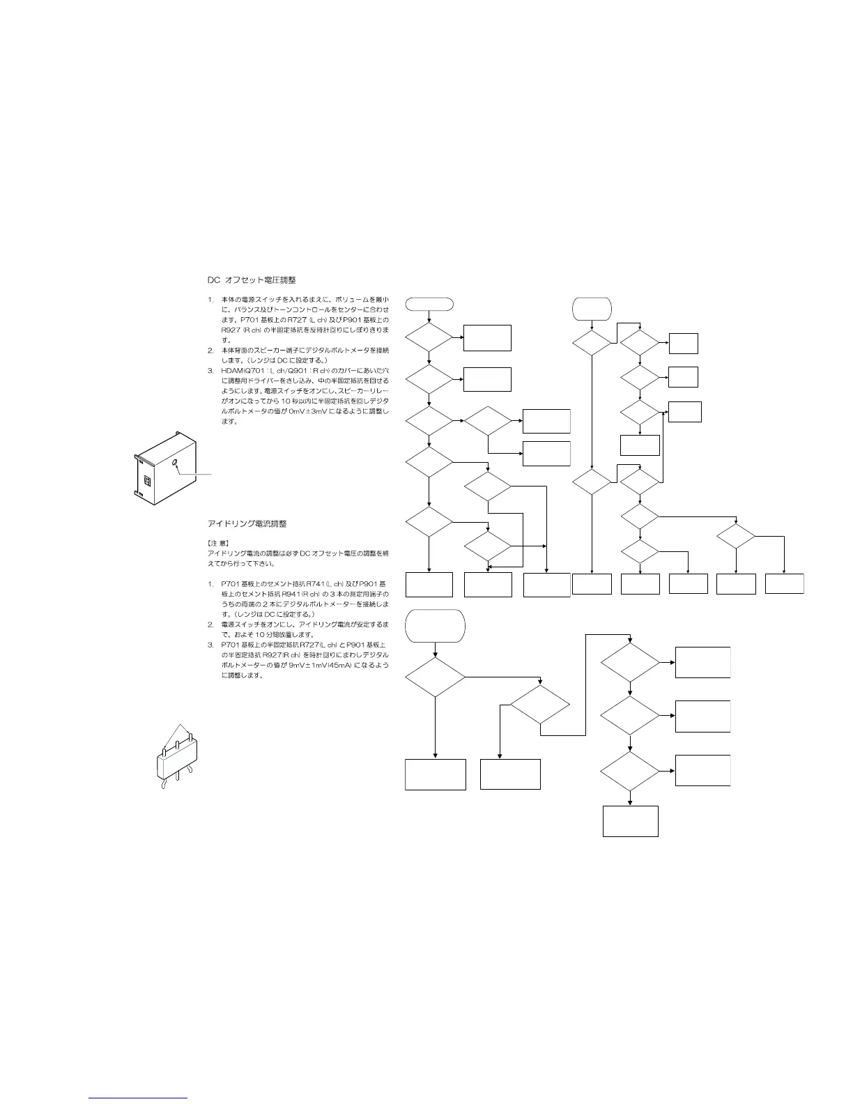
3. Put an adjustment screw driver into the hole on the
cover of HDAMs(Q701:L ch/Q901:R ch) to adjust the
variable resister inside. Turn on the main power and
within 10 seconds after the speaker relay turns on adjust
the variable resister to 0mV±3mV of the digital voltage
meter reading.
10. IDLING CURRENT ALIGNMENT
REMARK
Idling current adjustment must be done AFTER DC offset
voltage adjustment is done.
1. Connect a digital voltage meter to the terminals that are
the two terminals at the both side out of three terminals
on the cement resisters R741(L ch) and R941(R ch). See
the fi gure below. (Set the meter at DC position)
2. Turn on the main power and wait about 10 minutes until
the idling current becomes stable.
3. Turn the variable resisters R727 on the PCB P701(L ch)
and R927 on the PCB P901(R ch) clockwise and adjust
those to become the readings of the digital voltage meter
to 9mV±1mV(45mA) .
11. TROUBLE SHOOTING
no
yes
no
yes
no no
yes yes
no
yes no
yes
no
yes no
yes
No Power
Standby LED
Lights up on
standby
FLD shows
ERROR
PWR1?
Supply +24V
to PU04 ?
PU04 has any problem.
QU01(76p or 77p) lnput
level is too Low.
Can P804
supply
+15VB?
Connection has
problem
To be check POWER ON
or PL signal
Main Transf(L001)
or Meter Lamp(MU30)
has any problem
Vkk or FL is not supplied
to PU04
Power supply circuite
(PB04)
has any problem.
To be check +5VL or
PDOWN signal
Supply
+15VB
to PU04?
P804 has
any problem
Can P804
supply
+24VB?
Temp Meter
Light On ?
Relay
(L872:P804)
control is
no no
yes yes
no
yes
no
yes
no
no
yes yes
no
yes no
no
yes
yes
No sound from
SPK on Analog
Stereo mode
Audio SW(PS04),
Volume, I/V amp(PG04)
has any problem.
Analog
S-Direct is
OK ?
Audio SW, Volume, &
Power Amp are OK
Q601,QD01(P604)
has problem
Test Tone is
OK ?
Audio SW, Volume, &
Power Amp are OK
P604 (QK01:ADC) has any
problem
Main in is
OK ?
P804(Power)
has problem
Pre output is
OK ?
Relay
(LG01:PG04)
control is
Connection has
problem
Can P804
Supply ±B or
±VB ?
To be check
PROTECT
signal ?
P704,P904
(Power amp)
has problem
Relay
(LN01:P804)
control is
to be check POWER
or SPK-OFF signal,
QN01 has problem
Connection has
problem
TAPE OUT
is OK ?
Volume, & Power Amp are
OK
PS04(QS01,02:Audio SW)
has any problem
no
no
yes
yes no
no
yes
yes
no
yes
No sound
from SPK on PCM
STEREO(Digital In)
Analog
S-Direct is
OK ?
to be check Main in
at SPK Output
Test tone is
OK ?
Pre output is
OK ?
Encode status
LED shows ?
96k PCM is
OK ?
Audio SW(PS04),
Volume, I/V amp(PG04)
has any problem.
DIR:QR01(P604)
has problem.
DAC circuite(P604)
any has problem.
DIR is OK.
DSP:Q601(P604)
any has problem.
DIR,DAC are OK.
DSP(601) input stage
has problem.
To be check QR06.

Related product manuals