13
Marathon Electric (a division of RBC Manufacturing Corp.) reserves the right to change specications and this manual without notice.
Revised 06/2011
DOWN
ClosingtheDOWNcontactacrossterminalsJ1-3 andJ1-4causestheactiveoperatingsetpointtodecrease.
Keeping the contact closed will continue to decrease the operating set point until the limit is reached. The limit
isdeterminedbythevalueenteredintheMaximumVoltageAdjusteldoftheWindows
®
software. This field is
adjustablein0.1%incrementsandallowsaninputrangeof0.0%to15.0%.TheeffecttheUPandDOWNcontacts
are having on the set point is displayed in the Windows
®
software.
Note: If power is removed from the DVR
®
2000E+, the settings from the remote UP/DOWN contacts will be lost.
DROOP_OFF
ClosingtheDROOP_OFFcontactacrossterminalsJ1-10andJ1-4disablesvoltagedroop.Anopencontact
enables voltage droop. This function enables reactive load sharing between generators operating in parallel.
EXCITATION_OFF
ClosingtheEXCITATION_OFFcontactacrossterminalsJ1-11andJ1-4disableseldexcitation.Anopencontact
enables field excitation. This function enables removal of excitation without removing power to the regulator.
Opening the EXCITATION_OFF contact will initiate a soft start and clear any alarm or fault conditions.
Communication Port
The communication port provides an isolated interface for user programming (setup) of the DVR
®
2000E+ through
the Windows® communication software. Connection is made to the female RS-232 (DB-9) connector with a user-
supplied, standard 9-pin cable. A Null modem cable is unacceptable.
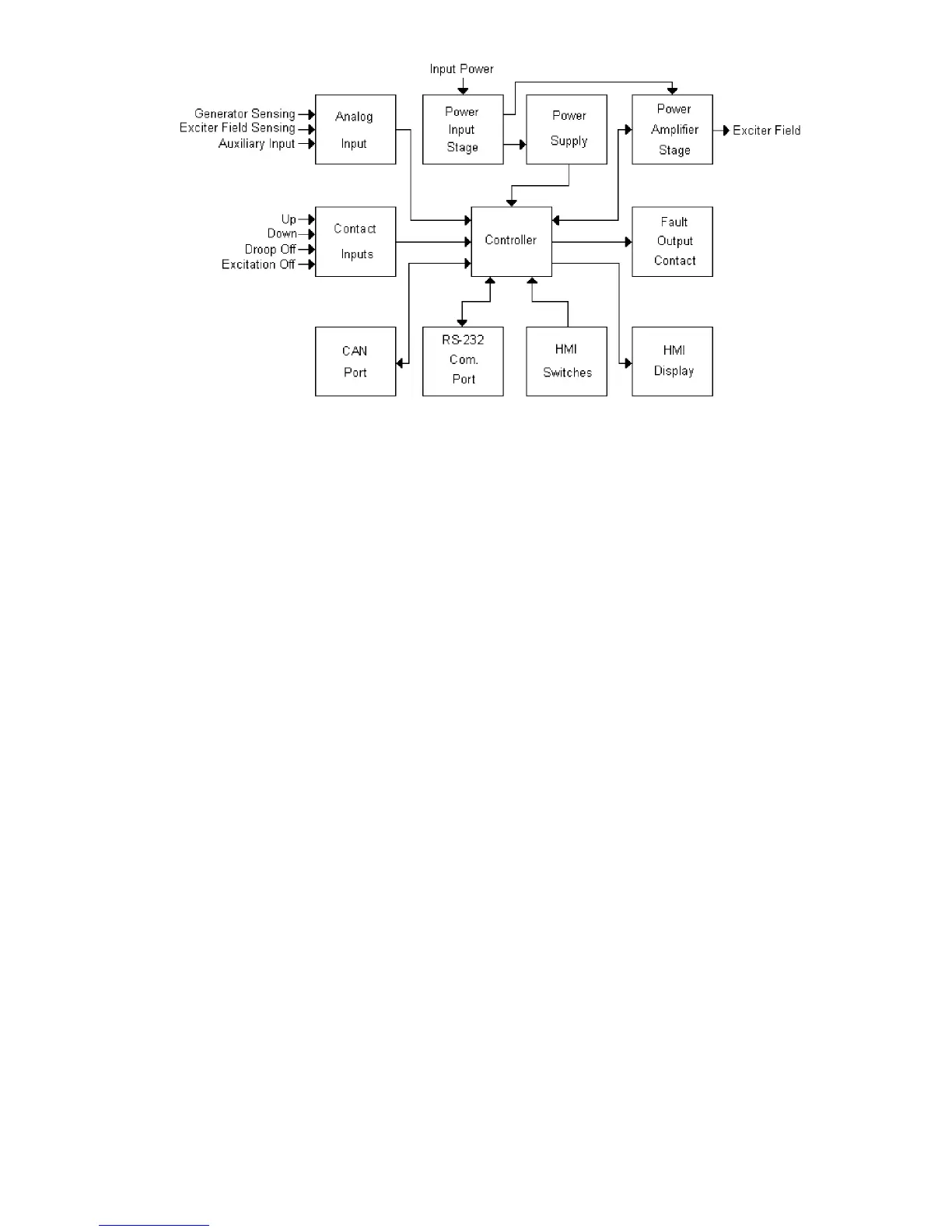
Figure 3-1. Simplified Block Diagram