77
Marathon Electric (a division of RBC Manufacturing Corp.) reserves the right to change specications and this manual without notice.
Revised 06/2011
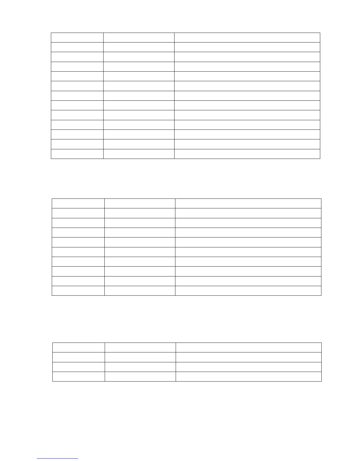
The following table should be used when making system connections to the regulator.
TableB-3.ConnectorJ1SystemConnections
The following table should be used when making MODBUS communication connections to the regulator.
Table B-4. MODBUS Communication Port Pin Functions
The following table should be used when making CAN communication connections to the regulator.
TableB-5.ConnectorJ3SystemConnections
Pin Number Name Description
1 AUX IN (+) Auxiliary input positive
2 UP UP contact input (active low)
3 DOWN DOWN contact input (active low)
4 CGND Input common
5 AUX_LOOP Auxiliarycurrentloopjumper
6 CONTACT1 Contact output
7 CONTACT2 Contact output
8 AUX_LOOP Auxiliarycurrentloopjumper
9 Reserved
10 DROOP_OFF Droop disable contact input (active low)
11 EXCITATION_OFF Excitation disable contact input (active low)
12 AUX IN (-) Auxiliary input negative
Pin Number Function Name
1 N/C
2 Receive Data RXD
3 Transmit Data TXD
4 Data Terminal Ready DTR
5 Signal Ground GND
6 Data Set Ready DSR
7 Ready To Send RTS
8 N/C
9 N/C
Pin Number Function Name
1 CAN High CAN_H
2 CAN Low CAN_L
3 CAN Ground CAN_GND