Series TT01 Digital Cap Torque Testers User’s Guide
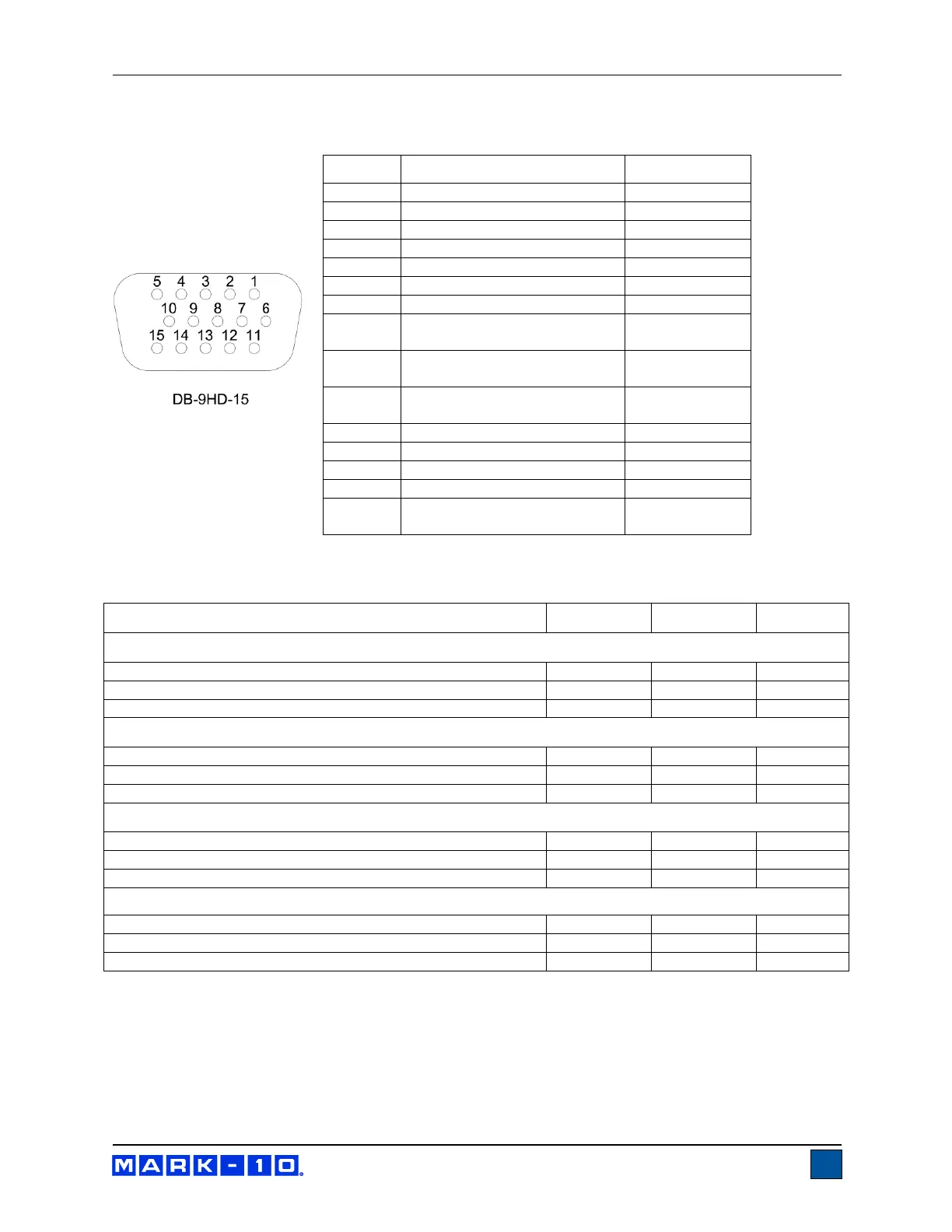
12.5 I/O Connector Pin Diagram (female)
* The output assignments depend on
several factors described in the table below. Output functions always reference the primary reading on
the display, regardless of the current mode.
Upper and Lower Set Points are Clockwise
Greater than or equal to upper set point
Between upper and lower set points
Less than or equal to lower set point
Upper and Lower Set Points are Counter-clockwise
Greater than or equal to upper set point
Between upper and lower set points
Less than or equal to lower set point
Upper Set Point is Clockwise, Lower Set Point is Counter-clockwise
Greater than or equal to upper set point, in clockwise
Between upper and lower set points
Greater than or equal to lower set point, in counter-clockwise
Upper Set Point is Counter-clockwise, Lower Set Point is Clockwise
Greater than or equal to upper set point, in counter-clockwise
Between upper and lower set points
Greater than or equal to lower set point, in clockwise
Counter-clockwise Overload
Mitutoyo Clock
Output Bit 2
Mitutoyo Data
Output Bit 0
Mitutoyo Request
Input Bit 3
Mitutoyo Ready
Output Bit 1

 Loading...