9
3.1.2 Installation of forks with carbon fi bre steer tube - crown
assembly on the frame
WARNING!
This is a one piece carbon steerer tube-crown assembly. Any
attempt to modify, or alter this assembly may result in serious
injury and/or death. To ensure safety and proper use, this
product should be installed by a qualifi ed bicycle mechanic
and requires the following special care:
Visually inspect assembly before and after every ride.
No frays, nicks, cuts, cracks or wear in the carbon should be present
on steerer tube crown assembly. If present, do not ride, replace
assembly immediately.
Use only a 39.8mm crown race. Do not damage carbon surface
when installing or removing crown race.
Cut steerer fl ush with stem. When cutting steerer , wrap surface
with masking tape and use a fi ne blade (32-tooth minimum).
Remove frays and burrs from cut area with fi ne sandpaper (400
grit minimum).
Do not use a star nut. Use only Marzocchi expansion style plug. Do
not exceed 11.3 N-m (100in-lb) torque on the expansion plug bolt.
Do not exceed a 30mm stack height when installing the stem.
Do not exceed stem manufacturers torque specifi cations.
Stem may not have any sharp edges in contact with carbon
steerer.
Stems with clamping area less than 50mm are not recommended.
WARNING!
Noncompliance with these care instructions may cause
damage to the carbon crown steerer, loss of control of the
bicycle, and could result in serious injury and/or death.
3.2 Installing the brake system
Installing the brake system is a delicate and critical operation that
must be carried out by specialized personnel.
WARNING!
Brake system installation requires specialized
knowledge, tools and experience. General mechanical
aptitude may not be suffi cient to properly install your
brake system. Please have your brake system installed
only by an authorized Marzocchi Service Center.
Improper installation of a disk brake system can overstress
the caliper mountings, which may cause the caliper
mountings to break, resulting in loss of control of the bicycle,
an accident, personal injury, or death. Be sure that the brake
system installation is also performed in strict compliance with
the instructions provided by the brake system manufacturer.
Use only brake systems that comply with the forks specifi cations,
taking into consideration the contents of the summarizing tables
contained in this manual.
WARNING!
Make sure, before every ride, that the brake cable of the disk
brake system is correctly connected to the proper mounting
(see 4B & 4C in Table 4).
WARNING!
The front brake line must be properly secured to the mounting
tab provided on the lower casting arch. All cables and
housings on the bicycle should never touch or rub any part
of the fork during use.
3. INSTALLATION
3.1 Installing on the frame
The fork is supplied with an threadless steer tube to be cut according
to the frame size the fork is being installed on. Installing the fork on
the bicycle frame is a delicate and critical operation that must be
carried out by specialized personnel.
WARNING!
Suspension system installation requires specialized
knowledge, tools and experience. General mechanical aptitude
may not be suffi cient to properly install your suspension
system. Please have your suspension system installed only
by an authorized Marzocchi Suspension Center. Improper
installation can result in failure of your Marzocchi Suspension
System, an accident, personal injury, or death.
The interference of the cylinder on the base and the play between
the cylinder and frame are particularly critical factors for the safety of
the operator. For this reason, maintenance and installation must be
performed exclusively at authorized technical assistance centres,
which have suitable equipment and specifi c knowledge.
NOTE
There is a protective fi lm to be removed before use to protect the
stickers.
NOTE
When installing the remote system, only use the cable housing
supplied or similar housing with the same diameter. Only use
derailleur housing. Do not use brake cable housing or any housing
with a spiral wind under the outer coating.
3.1.1 Installation of dual crown forks on the frame
WARNING!
On all dual crown Marzocchi forks, the lower crown is clamped
to the stanchions using bolts. In this case, please be aware of
the following precautions during installation.
On double crown forks, the lower part of the lower crown must
be positioned above the MIN notch and maximum 2 mm above
the reference.
The distance between the infl ated tire and the lower part of the lower
crown, when the fork is at travel’s end, must be at least 4 mm.
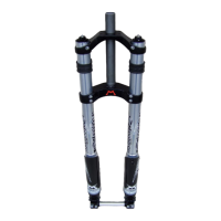
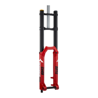
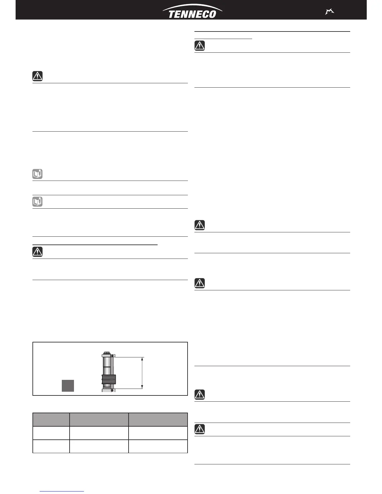
The length of the steer tube between the two crowns (see Picture
2A) must be between than the values H min and H max shown
in Table 3.
A
H
Picture 2 - Dual crown forks installation on the frame: (2A) Steer tube length
between crowns
Model H min H max
380 92 mm 148 mm
888 109 mm 160 mm
Table 3 - Steer tube length between crowns