VIBRATION TRANSMITTER-VT7S12E
Ref No: mVTD/om/201
Issue No: 02
User’s Manual - 13 -
Follow Table 22(Input type for
All Channel)
Acceleration(for all
channel)
Process value
range high setting
(PV high > PV
low)
Follow Table 22(Range High
for All Channel)
Process value
range lower
setting
Follow Table 22(Range Low
for All Channel)
Decimal Point
Setting Only
applicable for
Linear input type
is selected
Relay
Logic(Applicable
for All Relay)
nl / fs
(Normal / Fail Safe)
0:Noraml
1:Fail Safe
Al / Co
(Alarm / Control Output)
0:Alarm
1: Control Output
Relay
Function(Applicab
le for All Relay)
AL / TR
(Alarm / Trip )
0:ALARM
1:TRIP
Relay
Delay(Applicable
for All Relay)
Relay Open
sensor(Applicable
for All Relay)
up / Dn
(UP / Down)
0:DOW N
1:UP
Relay mapping
(Applicable for All
Channel)
No. of Slot For
RPM Input Type
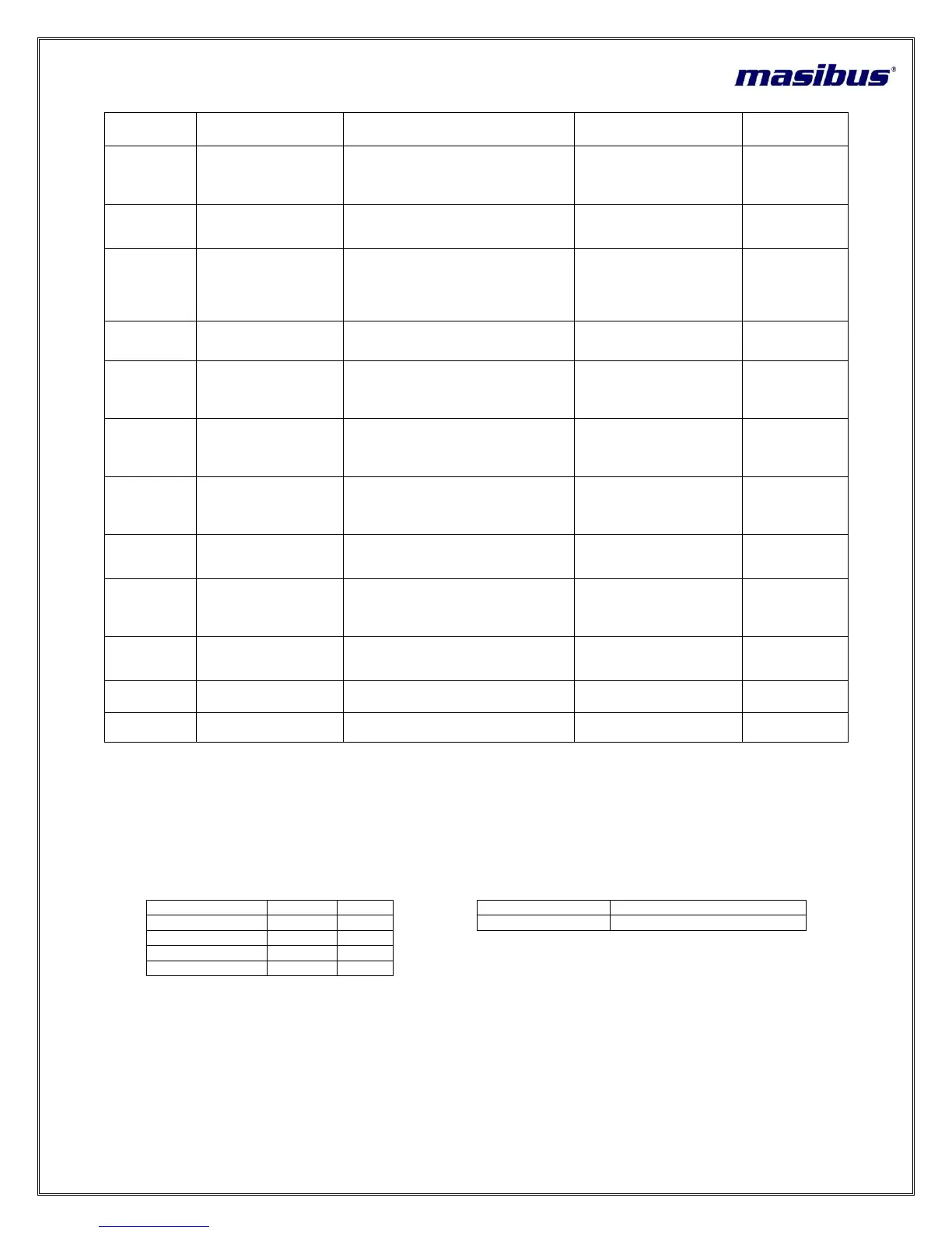
Table 6 Level – 2 Parameter Description
7.2.1 Relay Configuration
Relay configuration depends on selection of Relay group i.e. Relay group 1 or Relay group 2 or Relay group 4 in Level-3.
Relay Group - 1:
If Relay group – 1 is selected, there will be only one group of relay. That group has four relays. (G-1). G-1 means RELAY 1,
RELAY 2, RELAY 3 and RELAY 4
Table 7 Relay Group – 1 Configuration Detail
Example:-
Note:- None means no group is selected for particular channel.
Relay Group - 2:
Low ON (L) or High ON (H)
Relay Type can be selected as shown below: