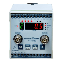
VIBRATION TRANSMITTER-VT7S12E
Ref No: mVTD/om/201
Issue No: 02
User’s Manual - 22 -
10. MODBUS COMMUNICATION DETAIL
The MODBUS Communications protocol as RS-485 interface module is installed. Only RTU mode is supported. Data is
transmitted as 8-bit binary bytes with 1 start bit, 1/2 stop bit and optional parity checking (None, Even, Odd). Baud rate may be set
to 9600 and 19200.
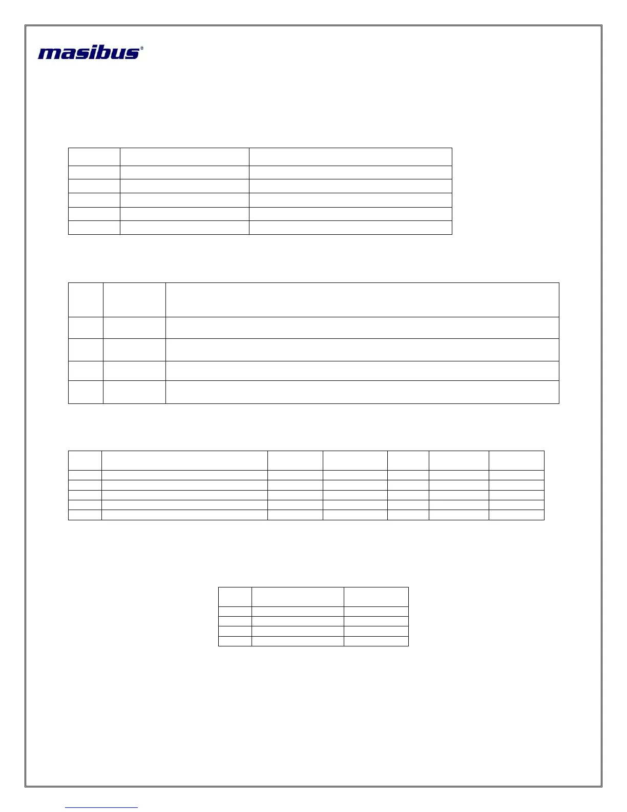
Function code use for Modbus:
Use to write output and input status
Use to read PV for 4-channels
Use to read programmable registers
Use to set or reset the coil
Use to write programmable register
Table 15 Modbus Function code description
Exception responses for Modbus:
Table 16 Exception codes
Modbus Parameter Details for Process Value:
Table 17 Modbus Parameter Details for Process Value
Modbus values for OPEN, OVER, UNDER and SKIP Conditions:
Table 18 Details of abnormal Conditions of Process Value
The function code received in the query is not an allowable action for the slave. If a Poll Program
Complete command was issued, this code indicates that no program function preceded it.
The data address received in the query is not an allowable address for the slave
A value contained in the query data field is not an allowable value for the slave
When Master device write some parameters to Slave device If slave device busy it will send 06 code to
indicate slave device is busy.