19
0º on the bevel scale. Retighten the screw.
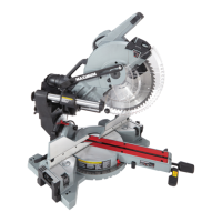
CHECKING THE ALIGNMENT OF THE RIP FENCE TO THE BLADE
(See Fig. 16a)
1. Unplug the saw, and remove the
blade guard assembly.
2. Raise the locking lever in order to
allow the rip fence to be moved.
3. Place the framing square beside the
blade, and move the rip fence up to
the square. Note the measurement
on the rip scale.
4. Move the fence back, and rotate
the framing square 180ºin order to
check the other side.
5. If the two measurements are not the same, loosen the two screws on the
fence, and then align it.
6. Retighten the two screws.
7. Make two or three test cuts using scrap wood. If the cuts are not true,
repeat the process.
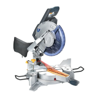
SETTING THE RIP FENCE SCALE INDICATOR TO THE BLADE (See Fig. 16b)
Begin with the blade at 0 angle
(straight up)
Unplug the saw.
1. Unplug the saw.
2. Loosen the rip fence by lifting the
locking lever.
3. Place the rip fence on the saw table
so that it lightly touches the right
side of the saw blade. Lock the rip
fence in place.
4. Loosen the screw and adjust the indicator so that the red line is located
over the “0” line on the front rail of the right-hand rip scale. Retighten the
screw.
USING THE RIP FENCE (See Fig. 17)
1. Unplug the saw.
2. Place the front lip of the rip fence on the front of the saw table, and push it
slightly toward the back of the unit.
Fig. 16b
Fig. 16a
Saw blade
Clamp screw
Rip fence
Rip fence
 Loading...