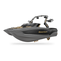
Proper control of MasterCraft boats extends beyond the steering
wheel. Each boat is equipped with multiple gauges that provide infor-
mation to guide the operator in maintaining control. There are also
a variety of switches and buttons within the boat that control vari-
ous functions from comfort to watersports enhancement to safety-
related features. It is important for the boat owner and/or operator
to become familiar with all gauges and switches in the boat, the func
-
tionality of each, and how to respond to alarms and warnings that the
instrument panel may provide.
In the Guide to Individual Models section of this Owner’s Manual is
a listing of the locations of gauges and switches for the various model
instrument panels. Operators should match up these listings with the
actual panel. Prior to boating, owners and operators should also review
and understand the following section regarding the boat’s electrical
components and operations through the battery or batteries, as well as
the circuit breaker system. A thorough understanding of these systems
is critical to avoiding potential issues that may arise during an outing.
The following is an explanation of the functionality of the gauges
and switches that are listed for the various models.
12-Volt Receptacle
(All Models; Some May Have
Multiple Receptacles)
MasterCraft boats have one (1) or more 12-volt
receptacles. Examine your boat to determine wheth-
er there are additional outlets. Prior to plugging any
accessory into a 12-volt receptacle, ensure that the
device is designed for use when connected to a 12-volt receptacle and
will not be damaged by the connection to the receptacle.
Accessory Switches
(All Models—Actual Switch Usage Will Vary)
Instrument panels may be equipped with Acces-
sory Switches. In some instances, the indicator may
be labeled with the name of the accessory, such as
“Heater.” Accessory switches are two-position or
three-position switches. Toggling will turn a con-
nected accessory ON and OFF.
i n st rum e n t gau g es an d switc h es
Aft Light Switch
(Models Equipped with Optional Tower
Lights)
The location of the aft light switch (where
equipped) will vary by model and should be lo-
cated by the operator. In some instances, there
may be two (2) switches. In all instances, the lights
operate by using two-position switches, one posi-
tion for ON and the other for OFF.
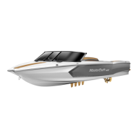
AM/FM Stereo,
CD Player, Remote
Control, iPod and MP3
Player Connections
(Stereo Standard Installation on
X-Series; Optional on All Other
Models; Remote Control on Arm-
rest, iPod and MP3 Player Connections with Stereo Installation)
Boats may be equipped with a range of entertainment opportunities
from radios and CD players to connections for personal devices. ALL
radio and CD players will be located within the glovebox of the boat.
Remotes may be in the armrest or on the transom.
The iPod interface option features a cable located inside the
glovebox that allows the unit to simply be plugged in and run off the
boat’s electrical system. An optional plug-in location for MP3 players
is available. Be aware that all such devices are a drain on the boat’s
battery and electrical system. Care should be taken to avoid excessive
usage of such devices and by responding to any alarms that sound so
that the boat’s battery(ies) does not become fully discharged.
Anotheroptionisawirelessstereoremotethatwilloatifacci-
dentally dropped overboard. The remote can also double as a key fob
for a limited number of keys.
The stereo and components come with a separate manual ex-
plaining operation of the devices. Please review and become familiar
with the equipment.
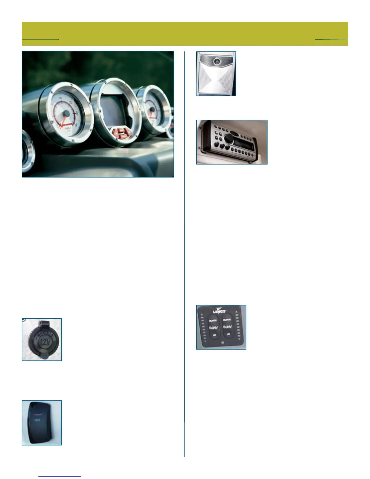
Attitude Adjustment
or Trim Tab Switch
(All MariStars and CSX 265)
MasterCraft utilizes Lenco attitude adjust-
ment plate kits on several models. Dual plate
kits are available on the MariStar 280, X-80,
280 STS and CSX 265 models; a single plate
kit is used on the MariStar 200, X-2, 215, X-15,
230, X-30, 235, X-35, 245 and X-45. On the dual attitude adjustment
plate system, the plates operate independently of each other to provide
optimalperformancebyredirectingwaterownearthetransomofthe
boat. These plates have been designed to improve the overall attitude
of a boat. If used properly, the plates will improve the ride, reduce drag,
increasespeedandimprovethefuelefciencyoftheboat.
The operation of the attitude adjustment plates is basic. The plane
or planes are mounted with the actuator(s) on the transom of the
boat.Whentheplate(s)is/arelowered,thewaterowisredirected,
creating an upward force at the stern of the boat. When the stern
rises, the bow will lower.
Since these actuators are electromechanical, they provide an im-
mediate response at the touch of the switch. The switch adjustments
are based on the position of the bow. On the dual attitude adjustment
plate system, the right side of the switch controls the starboard plate
mastercraft 2010 ow n e r ’s m anual • page 5-1
 Loading...