29
TM
ADJUSTMENTS
TM
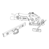
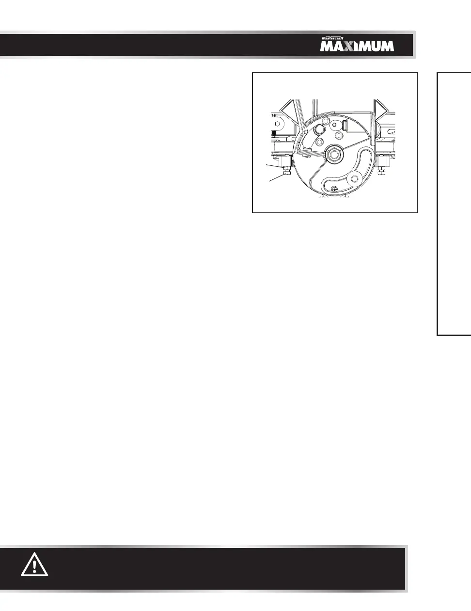
45° Right Bevel Positive Stop Adjustment
(Fig. 15, 16, 17)
• Loosen the bevel lock handle (1) and set
cutting arm at 45° angle. (Fig. 15)
• Pull out the 33.9° detent pin (3) and tilt the
cutting arm completely to the right. (Fig. 16)
• Using a combination square, check to see if
the blade is 45° to the table.
• If the blade is not 45°
to the mitre table,
tilt the cutting arm to the left, loosen the
locknut (1), and turn the adjustment bolt (2)
in or out to increase or decrease the angle.
(Fig. 17)
• Tilt the cutting arm back to the right, and
recheck alignment.
• Repeat above steps until the blade is 45°
to the table. Once alignment is achieved,
tighten the locknut (1). (Fig. 17)
45° Left Bevel Positive Stop Adjustment
(Fig. 15, 16, 17)
• Loosen the bevel lock handle (1) and set
cutting arm at 45° angle. (Fig. 15)
• Pull out the 33.9° detent pin (3) and tilt the
cutting arm completely to the left. (Fig. 16)
• Using a combination square, check to see if
the blade is 45° to the table.
• If the blade is not 45°
to the mitre table,
tilt the cutting arm to the right, loosen the
locknut (3), and turn the adjustment
bolt (4) in or out to increase or decrease
the angle. (Fig. 17)
• Tilt the cutting arm back to the left, and
recheck alignment.
• Repeat above steps until the blade is 45°
to the table. Once alignment is achieved,
tighten the locknut (3). (Fig. 17)
Fig. 17
WARNING:
To avoid injury from an accidental start, make sure the switch is in the OFF
position and the plug is not connected to the power source outlet.
1
2