35
TM
ADJUSTMENTS
LASER GUIDE ADJUSTMENT
(Fig. 28, 29, 30, 31)
NOTE: All the adjustments for the operation
of this machine have been completed at the
factory. Due to normal wear and use, some
occasional readjustments may be necessary.
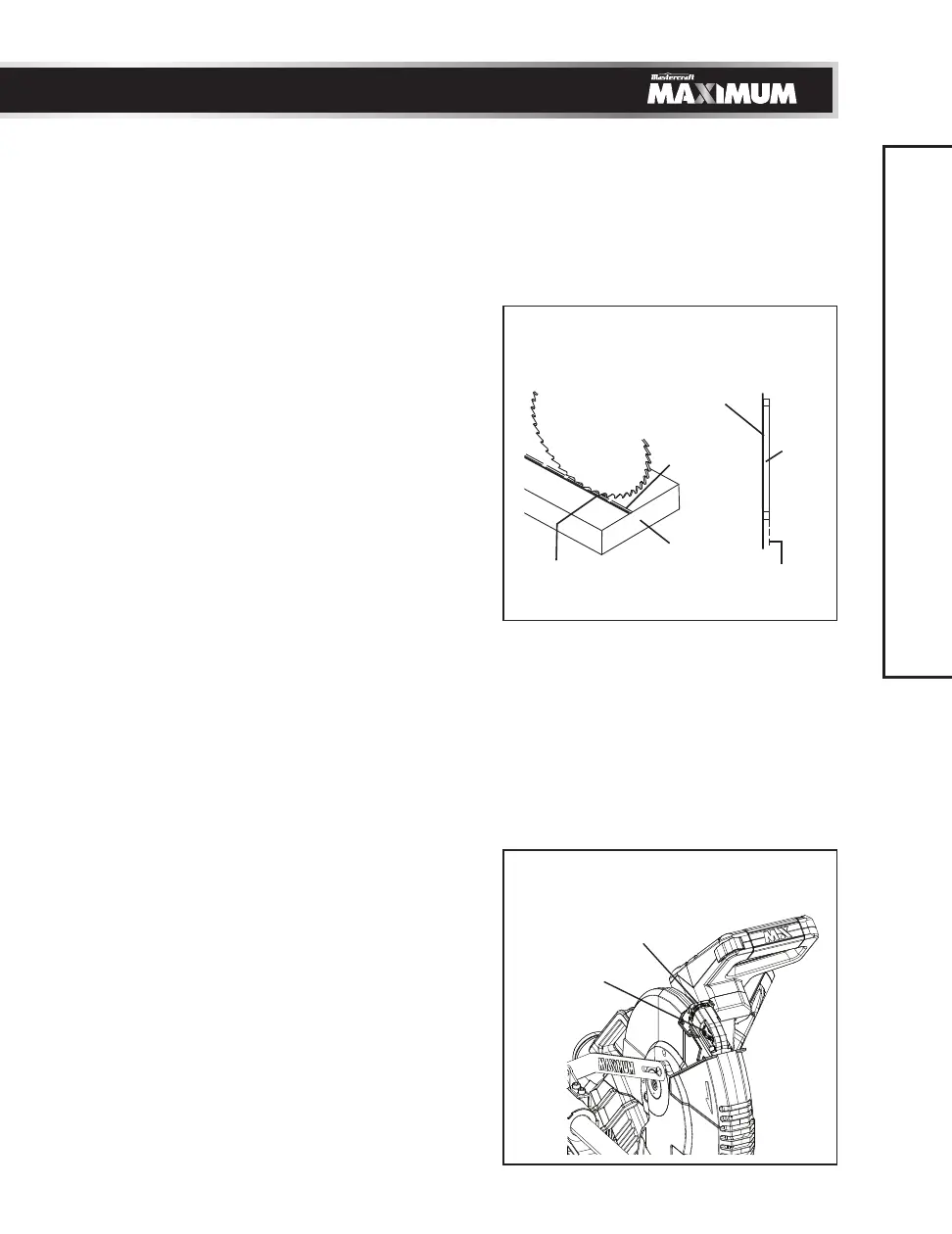
A. Checking Laser Beam Alignment (Fig. 28)
• Set the saw to a 0° mitre and 0° bevel
setting.
• Take a board and using a straight edge (not
included), mark a 90° line on the top and
front of the board. This line will serve as a
“pattern line” for all laser beam alignments.
Place the board on the saw table.
• Carefully lower the cutting head down to
align the saw blade with the pattern line.
Position the saw blade to the left, centre or
right side of the “pattern line” depending
on your preference for the laser beam
location.
• With the saw plugged in, turn on the laser
guide. Your saw has been preset with the
laser beam to the left side of the blade.
• Looking at the front of the board, if the
laser beam is not parallel to the “pattern
line” please follow the instructions listed
below under Procedure A.
• Looking at the top of the board, if the laser
beam is not parallel to the “pattern line”
please follow the instructions listed below
under Procedure B.
B. Adjusting the Position of the Laser Beam
Procedure A (Fig. 29, 30)
• Slightly turn the laser vertical adjustment
knob (1) to adjust the vertical angle of the
laser beam on the front of the board. When
the laser beam angles from left to right,
turn the laser vertical adjustment knob (1)
clockwise; if the laser beam angles right to
left, turn the laser vertical adjustment
knob (1) counter-clockwise until the laser
beam is parallel with the vertical
“pattern line.”
Fig. 29
Fig. 28
1
2
Laser beam
Cutting line
TOP VIEW
Blade
Laser beam
Workpiece
Cutting
line