4.2 Protections
The Mass Combi Ultra is protected against overload, short
circuit, overheating and under and over voltage. You can
detect failures from the front panel or from the MasterBus
control panel.
CAUTION!
The Mass Combi Ultra is not protected against
reversing polarity of the DC-input, AC voltage on
the DC-input and extreme over voltage (>300
VAC ) on the AC-input or AC-outputs.
4.2.1 Output overload or short circuit
In case of overload or short circuit during inverter mode,
the Power bar top LED illuminates red and the output
voltage of the Mass Combi Ultra is limited. Mass Combi
Ultra shuts down if this overload or short circuit lasts over 5
seconds. The Mass Combi Ultra will automatically restart
after shutdown. After 5 failed start attempts the Mass
Combi Ultra shuts down permanently, the Power bar top
LED and the Charge bar bottom LED stay blinking red. You
can restart the Mass Combi Ultra only by switching the unit
manually off and on with the main switch on the Mass
Combi Ultra after the overload or short circuit is removed.
4.2.2 Overheating
In the event of overheating the Mass Combi Ultra inverter
shuts down, the charger reduces charge current.
Overheating is most likely caused by:
heavy or non-resistive loads operating for a longer
period.
high ambient temperature.
disrupted air flow (dust or too little space).
As soon as the temperature drops below the factory default
threshold, the inverter is powered up automatically or the
charger resumes its charge current.
4.2.3 Under and over voltage
The AC-input of the Mass Combi Ultra is, within limits,
protected against over and under voltage. See
specifications. If the AC-input voltage is out of operating
range, the Mass Combi Ultra will switch to inverter mode,
disconnecting both AC inputs and it will switch back if the
AC-input voltage is within range again. The DC-input of the
Mass Combi is also protected against over and under
voltage. See specifications. The Mass Combi Ultra
switches off if the DC-input voltage is out of range.
4.2.4 Dynamic DC input window
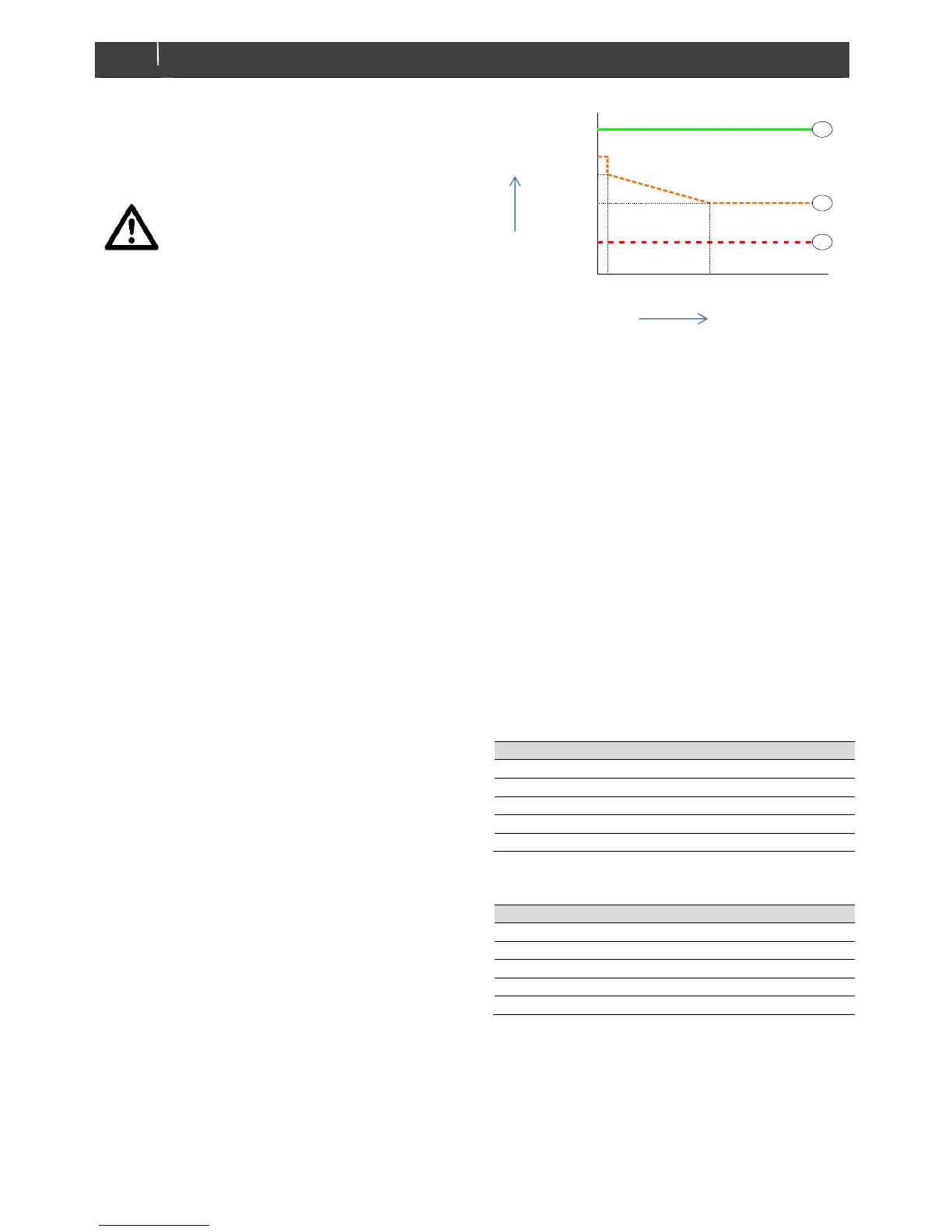
Figure 4-2: Dynamic DC input window
The Dynamic DC input window is used to switch off
depending on both the battery voltage and current. The
reason for this is that low current loads cause a small
voltage drop but they are responsible for severe battery
damage.
Shown in figure 4-2 is the graph for a 24 V lead acid
battery. The graph shows three lines:
(1) Low voltage switch on. Above this voltage the inverter
switches on.
(2) Low voltage switch off with delay. Below this line the
inverter switches off after a delay.
(3) Low voltage switch off without delay. Below this line
the inverter switches off without delay.
4.3 Operation policies
Via MasterBus configuration, the preferred behaviour of AC
in and outputs can be set.
4.3.1 AC input policy
 Loading...