5 INSTALLATION
During installation and commissioning of the Mass Combi
Ultra, the Safety Guidelines & Measures are applicable at
all times. See chapter 2 of this manual.
5.1 Unpacking
In addition to the Mass Combi Ultra the delivery includes:
a battery temperature sensor;
this user manual;
MasterBus terminating device.
After unpacking, check the contents for possible damage.
Do not use the product if it is damaged. If in doubt, contact
your supplier.
Check from the identification label (see section 1.6)
whether your Main battery voltage is the same as the DC-
input voltage of the Mass Combi Ultra (e.g. 24 V main
battery set for a 24 V input voltage). Also check that the AC
output voltage and output power of the Mass Combi Ultra
complies with your system and loads.
5.2 Environment
Obey the following stipulations during installation:
The Mass Combi Ultra is designed for indoor use only.
Ambient temperature: -25 ˚C to 60 ˚C, (power derating
above 40 ˚C).
Maximum usage/installation height: 2000 m.
Humidity: 0-95 % non-condensing.
Mount the Mass Combi Ultra on a solid surface, with
the connecting cables downwards.
Make sure that the hot air produced during operation
can be discharged. The Mass Combi Ultra must be
mounted in such a way that obstruction of the airflow
through the ventilation openings will be prevented.
No objects must be located within a distance of 10 cm /
4 inch around the Mass Combi Ultra. Keep at least 15
cm / 6 inch free space below the Mass Combi Ultra.
Do not locate the Mass Combi Ultra in the same
compartment as the batteries.
Do not install the Mass Combi Ultra straight above the
batteries because of possible corrosive fumes.
5.3 Wiring
The wiring is connected inside the connection
compartment. If necessary, the wiring can be fed from the
top to the bottom side of the cabinet along the back of the
cabinet.
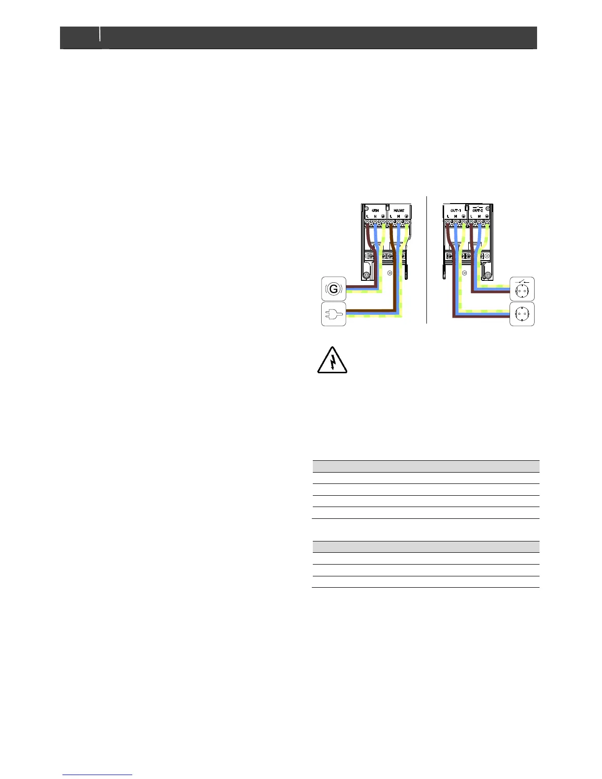
Always use the strain reliefs to fix the wiring. Fix the phase
line wire to terminal L, the neutral wire to terminal N and
the ground wire to terminal PE, see figure 5-1.
Figure 5-1: AC terminal connections
 Loading...