6 CONFIGURATION
The Mass Combi Ultra is provided with two groups of DIP-
switches to adjust the Mass Combi Ultra according to the
specifications of the electrical installation, see figure 6-1.
DIP-switch settings are 0 for default values. The Mass
Combi Ultra also features the more sophisticated
MasterBus configuration.
Previously done MasterBus settings are overruled by the
DIP-switch settings and they are greyed out in the menu.
When a DIP-switch is set to 0, the corresponding
MasterBus setting becomes default too, regardless the
previous setting.
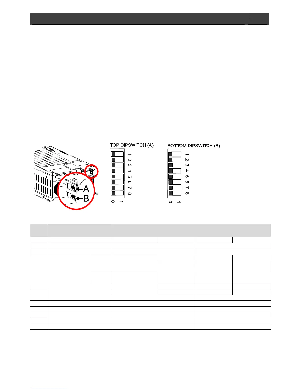
6.1 Configuration via DIP-switches
The DIP-switches are located in the connection
compartment. Figure 6-1 shows the location of the DIP-
switches and the print on the inside of the front cover plate.
6.1.1 Ground relay
For safe installation:
Residual Current Devices (RCD) must be integrated in
the AC inputs and AC outputs of the Mass Combi Ultra.
The neutral conductor (N) of the AC output of the
Inverter must be connected to the safety ground
(PE/GND) when the Mass Combi Ultra is working as an
inverter.
The ground relay function allows you to connect the
Neutral conductor (N) of the inverter output circuit to the
Safety Ground (PE / GND) automatically when the Mass
Combi is working as an inverter. Refer to local standards
on this issue.
Figure 6-1: DIP-switches and cover print
 Loading...