3 HOW IT WORKS
The Mass Combi Ultra is a multifunctional charger inverter.
It combines an inverter, a battery charger with secondary
(small) charger, an AC transfer switch and a solar charger*.
3.1 Principle
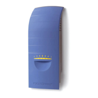
Figure 3-1: Working principle of the Mass Combi Ultra
3.1.1 User interface (1)
The Mass Combi Ultra user interface consists of a front
switch with status LEDS and MasterBus communication.
3.1.2 AC transfer switch (2)
This part of the Mass Combi Ultra regulates the AC energy
flow through the device. The generator (“GEN”) and mains
(“MAINS”) input are switched, as is AC output 2 (“OUT-2”).
All AC is connected to the inverter (3). If the MAINS plug is
disconnected and the Generator is not running, the inverter
takes over using battery power to provide AC power.
3.1.3 Inverter/ Main charger (3)
This part converts the AC power to DC for charging of the
main battery and it inverts the DC power from the battery to
supply AC to Output 1 and 2. (“OUT-1” and “OUT-2”).
* Models 12/3000-150 and 24/3500-100 only
3.1.4 Solar charger (4)*
The PV input (“SOLAR”) is meant for the connection of a
PV-array. The PV-voltage is converted to the proper DC
voltage for battery charging.
3.1.5 Secondary charger (5)
The secondary battery charger (“SEC”) is suitable for a
secondary battery set or as power supply.
3.2 Battery charger
The built-in battery charger is electronically controlled. It is
designed for optimal recharging of lead acid (flooded, gel,
AGM) and Li-ion batteries. Battery charging via AC or Solar
input is accomplished with Mastervolt’s 3-Step+ charging
algorithm. With an external AC source connected, the
Mass Combi Ultra charger also serves the functions of an
AC to DC converter to supply DC loads which are
connected to the batteries. Simple, automatic operation is
enabled by the microprocessor that is the brain of the
inverter/charger combination.
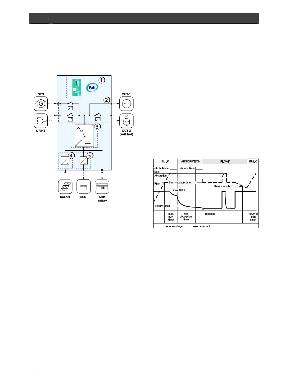
Figure 3-2: 3-step+ charge system
3.2.1 3-step+ charge system
See figure 3-2. The first step of the 3-step+ charge system
is the BULK phase, in which the output current of the
charger is 100 %, and the greater part of the battery
capacity is charged rapidly. The current charges the
batteries and gradually the voltage rises to the absorption
voltage, refer to the specifications. The duration of this
phase depends on the ratio of battery capacity to charger
current, the loads connected and the degree to which the
batteries were discharged to begin with.
The bulk phase is followed by the absorption phase.
Absorption charging ends when the battery is completely
full. Battery voltage remains constant throughout this stage
and the charge current decreases during charging of the
battery. With flooded batteries this stage lasts some four
hours, with gel and AGM around three. Once the battery is
100 % full or when the maximum absorption timer has
passed, the charger automatically switches over to the float
phase.
*
 Loading...