129
128
CHAPTER 9: PART REPLACEMENT GUIDE
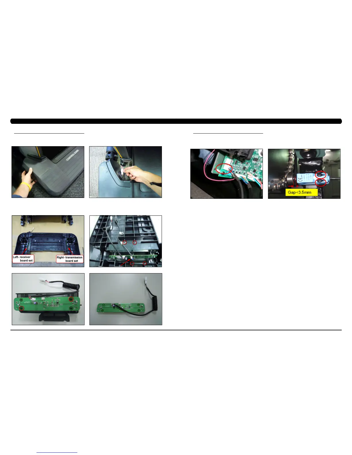
9.18 CONTROL ZONE SENSOR REPLACEMENT
1) Turn off power and disconnect the cord from the machine.
2) Pull up on the Control Zone carefully (Figure A).
3) Unplug the wire from the Control Zone and remove the Control Zone from the unit (Figure B).
4) Unplug the wire connector and remove the 4 screws to disassemble the receiver board set from the Control Zone (Figure D) and then remove
the 2 screws to disassemble the Control Zone sensor board (Figure E&F).
5) Reverse Steps 1-4 to install a new Control Zone sensor board.
6) Test the Climb Mill function as outlined in Section 9.23.
FIGURE A FIGURE B
FIGURE DFIGURE C
FIGURE FFIGURE E
CHAPTER 9: PART REPLACEMENT GUIDE
9.19 PROXIMITY SENSOR REPLACEMENT
1) Turn off power and disconnect the cord from the machine.
2) Rotate the 2 plastic clips counter-clockwise to remove the left side Matrix logo cover.
3) Remove the proximity sensor cable from the LCB, and cut any wire ties holding the cable to the frame (Figure A).
4) Remove the 2 screws holding the proximity sensor to the frame (Figure B), and remove the proximity sensor.
5) Reverse Steps 1-4 to install a new proximity sensor. note: The proximity sensor should be installed so that there is a gap of less than 3.5mm
between the sensor and the axle (Figure B).
6) Once the proximity sensor is installed, rotate the stairs at least 2 complete revolutions to make sure the sensor does not hit. note: The
sensor has a signal LED located near the mounting screws. The sensor should be mounted close enough to trigger this LED.
7) Test the Climb Mill for function as outlined in Section 9.23.
FIGURE A FIGURE B