61
10.3 ASSEMBLY INSTRUCTIONS - CONTINUED
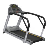
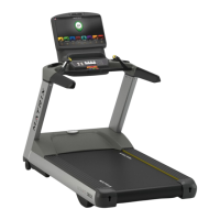
Motor Tray Connections - Only the console cable connections should need to be made,
but the other MCB connections are also shown.
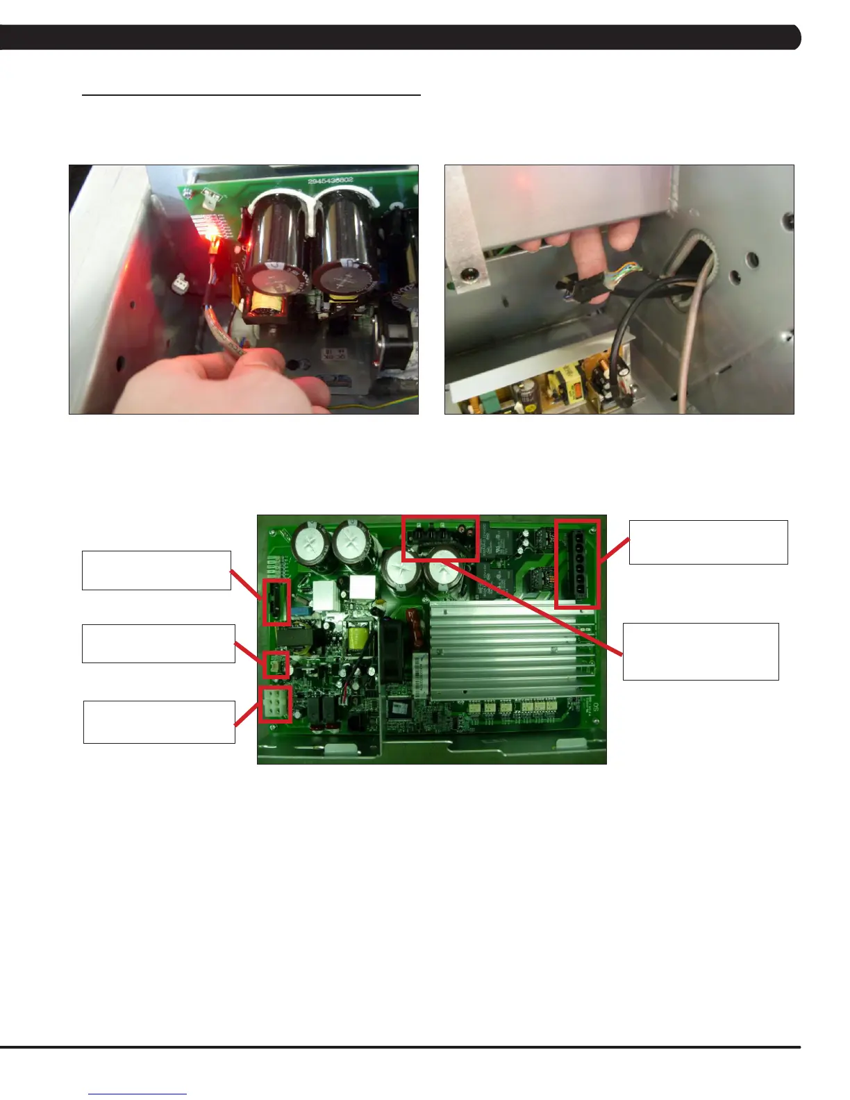
FIGURE C
J10 - 8 pin black connector
to the console.
J16 - 2 pin white connector
to the external fan.
J12 - 6 pin white connector
to the incline motor.
TB2 - 3 pin connector from
the choke (2 wires) and a
ground (1 wire).
TB1 - 5 pin connector from
the motor.
2 of the 3 console cable connections at the motor tray (the other is the coax cable).
CHAPTER 10: TREADMILL SPECIFICATIONS AND ASSEMBLY GUIDE
 Loading...