40 Chapter 4: Matrox Rapixo CXP hardware reference
Auxiliary signals
This section describes the auxiliary signals available on Matrox Rapixo CXP.
Auxiliary signals available on Matrox Rapixo CXP
The auxiliary signals of Matrox Rapixo CXP are acquisition path independent and
can be used to initiate on-board events (inputs) or can be transmitted to third-party
devices (outputs). You can also reroute an auxiliary input signal to a video source
via the CoaXPress trigger output signal.
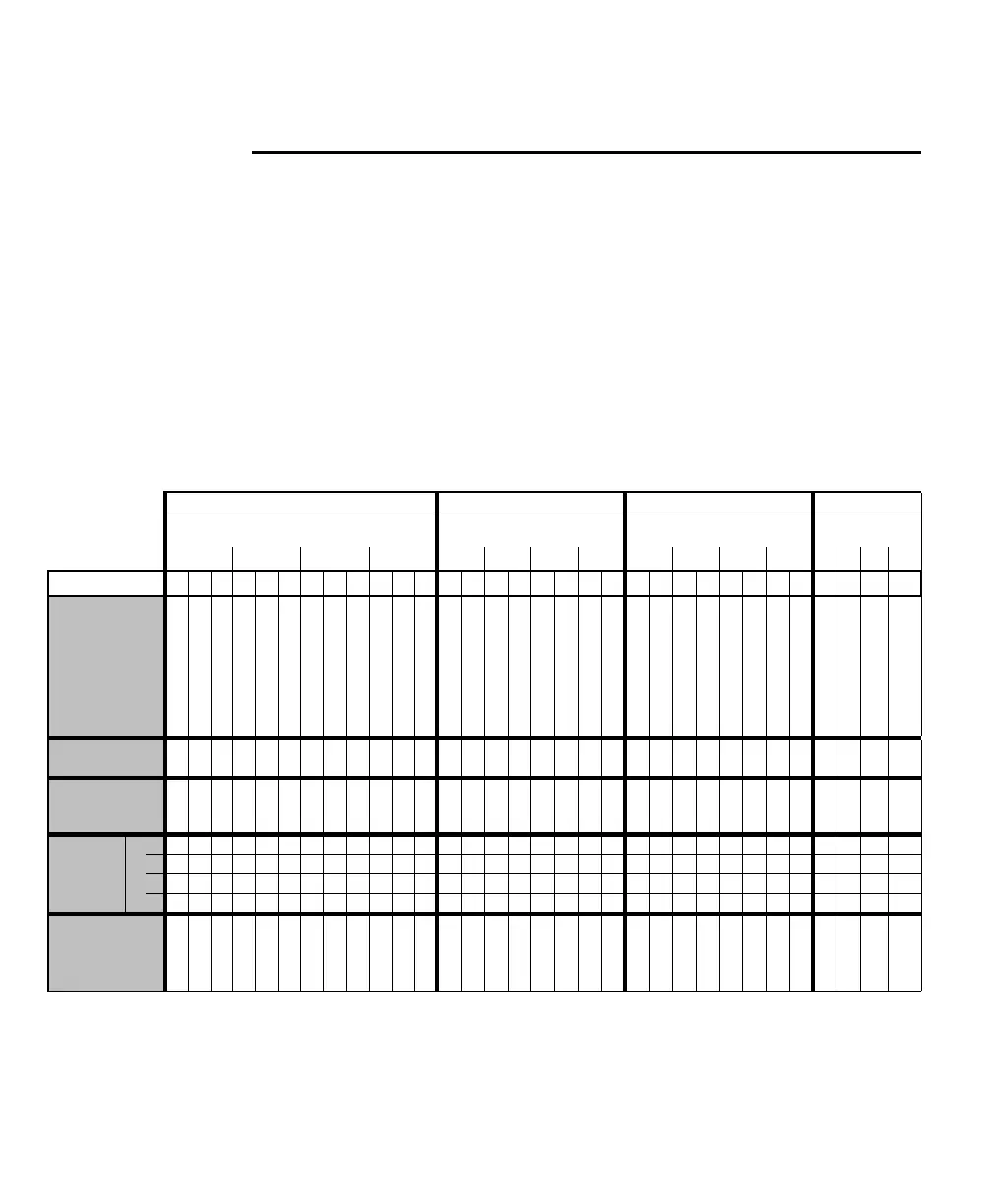
The following table summarizes the auxiliary functionality that Matrox Rapixo
CXP supports using its auxiliary I/O signals. The table also documents the MIL
constants to use.
TTL Aux I/O OPTO Aux In LVDS Aux In LVDS Aux Out
Aux I/O Connector Aux I/O Connector Aux I/O Connector Aux I/O
Connector
0 1 2 3 012301230123
M_AUX_IOn
*
4 5 6 121314202122282930 0 1 8 9 16172425 2 3 101118192627 7 15 23 31
Functionality that
can be routed or
received
AUX(TRIG)_TTL_IO_4
AUX(TRIG)_TTL_IO_5
AUX(TRIG)_TTL_IO_6
AUX(TRIG)_TTL_IO_12
AUX(TRIG)_TTL_IO_13
AUX(TRIG)_TTL_IO_14
AUX(TRIG)_TTL_IO_20
AUX(TRIG)_TTL_IO_21
AUX(TRIG)_TTL_IO_22
AUX(TRIG)_TTL_IO_28
AUX(TRIG)_TTL_IO_29
AUX(TRIG)_TTL_IO_30
AUX(TRIG)_OPTO_IN0
AUX(TRIG)_OPTO_IN1
AUX(TRIG)_OPTO_IN8
AUX(TRIG)_OPTO_IN9
AUX(TRIG)_OPTO_IN16
AUX(TRIG)_OPTO_IN17
AUX(TRIG)_OPTO_IN24
AUX(TRIG)_OPTO_IN25
AUX(TRIG)_LVDS_IN2
AUX(TRIG)_LVDS_IN3
AUX(TRIG)_LVDS_IN10
AUX(TRIG)_LVDS_IN11
AUX(TRIG)_LVDS_IN18
AUX(TRIG)_LVDS_IN19
AUX(TRIG)_LVDS_IN26
AUX(TRIG)_LVDS_IN27
AUX(EXP)_LVDS_OUT7
AUX(EXP)_LVDS_OUT15
AUX(EXP)_LVDS_OUT23
AUX(EXP)_LVDS_OUT31
Timer
(M_TIMERn
*
)
1/2/
3/4
1/2/
3/4
1/2/
3/4
1/2/
3/4
1/2/
3/4
1/2/
3/4
1/2/
3/4
1/2/
3/4
1/2/
3/4
1/2/
3/4
1/2/
3/4
1/2/
3/4
1/2/
3/4
1/2/
3/4
1/2/
3/4
1/2/
3/4
Trigger controller
affected by
input signal
††††††††††††††††††††††††††††
Bit of rotary
input
‡
Decoder
0 01
1 01
2 01
3 01
User output (bit of
static-user-output
register
M_USER_BITn
*
)
4 5 6 121314202122282930 7 15 23 31
*. MIL constant, where n corresponds to the number in the row.
†. There is no limit to the number of events that can be triggered simultaneously using the auxiliary input signals, nor is there a restriction on
which auxiliary signal can be used to trigger an event.
‡. A rotary encoder with quadrature output transmits a two-bit code. The table entries 0 and 1, therefore, denote bit position.