Auxiliary signals 41
Specifications of the auxiliary signals
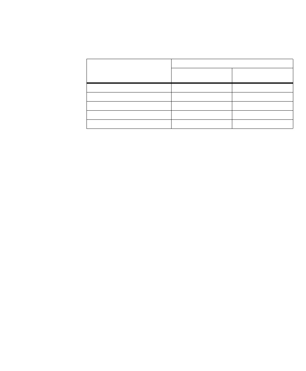
Matrox Rapixo CXP has auxiliary signals in the following formats:
When you route an external signal to an auxiliary signal or vice versa, verify that
the external signal meets the electrical specifications of the auxiliary signal.
When an auxiliary input signal is received in TTL format directly, it will be
clamped at a maximum of 5.7 V and at a minimum of -0.7 V to protect the input
buffer. Typically, the signal should have a maximum of 5 V and a minimum of
0 V. A signal over 2 V is considered high, while anything less than 0.8 V is
considered low.
The opto-isolated auxiliary input signals pass through an opto-coupler, a device
that protects the board from outside surges and different ground levels, and allows
the frame grabber to be totally isolated. The voltage difference across the positive
and negative components of the signal must be between 4.71 V and 9.165 V for
logic high, and between 0 V (recommended) and 0.8 V for logic low.
You can set the direction of an auxiliary I/O signal using the MIL-Lite function
MdigControl() with M_AUX_SIGNAL_MODE.
You can set up the auxiliary signals in the DCF. Alternatively, for most commonly
used functionalities, you can configure the auxiliary signals using the MIL-Lite
function MdigControl() (for example, with M_IO..., M_GRAB_TRIGGER...,
M_TIMER..., or M_ROTARY_ENCODER...
).
Signal Format
Total # of signals
Using both mDP connectors
(no cable brackets attached)
With cable bracket
TTL auxiliary input or output signals 6 12
Opto-isolated auxiliary input signals 4 8
LVDS auxiliary input signals 4 8
LVDS auxiliary output signals 2 4
Total number of auxiliary signals 16 32