CD 30 ÷ 520
52
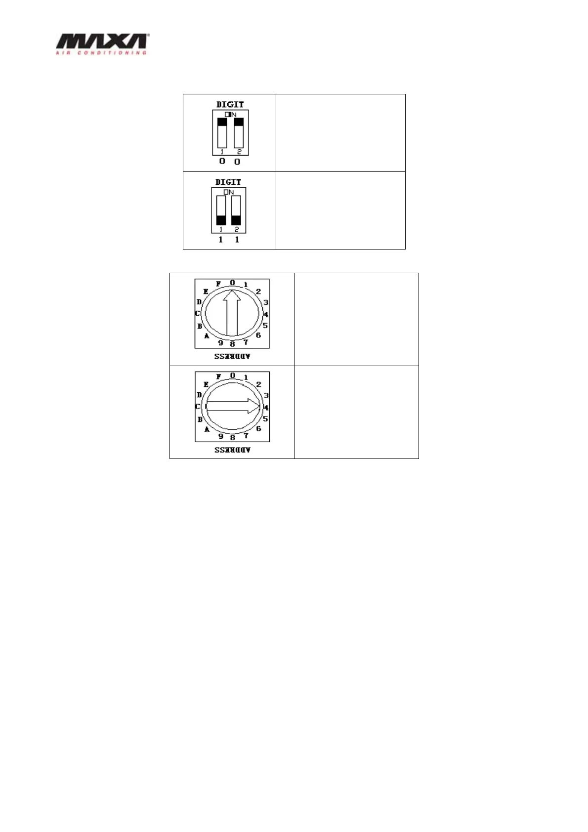
8——DIGIT Digital compressor selecting switch.
“00” presents selecting
digital compressor (as
the main unit.)
“11” presents selecting
constant compressor (as
the auxiliary unit.
9——ADDRESS
0 presents NO. 0 main
unit
1F presents NO 1
15 auxiliary units
respectively
10——COM(O)485 communication port (failure code E2).
11——COM(I) 485 communication port (failure code E2).
P, Q, E points of COM (O) and COM (I) are connected with each other for RS-485
communication.
If failure occurs between the linear controller and main module, all the units stop.
If failure occurs between main unit and auxiliary unit, the auxiliary unit with
communication failure will stop, and then the number of units online detected by the
linear controller will decrease; ”EA” will be displayed and the indicator lights will flash.
12——System A high-pressure protection & discharge gas Temperature switch protection
(protection code (P0),
System B high-pressure protection & discharge gas Temperature switch protection
(protection code (P2),
System A low-pressure protection (protection code P1)