DP-20 WEB GUIDE CONTROLLER ADDITIONAL USER MANUAL INSTRUCTIONS
05-14-2004 DP-20 WEB GUIDE CONTROLLER Figure Sheet 1-875
2
2-6
Features of the LCD Panel
LINE 4 While at the Operator Level, in Automatic mode, Servo
Center mode, or Manual mode, if Stroke Limits are set to ON, this
line flashes STROKE LIMIT if either one of the programmed stroke
limits is reached.
Motor List
LCD Indication Motor Resistor Typical Assembly
PITTMAN MTR 442K Pittman #14206C255 442K Von Weise #V03798AA62
Motor/Actuator
Parallel Output Matrix
OUTPUTS
STATUS B* A*
AUTOMATIC MODE - 1
STROKE LIMITS 1 -
* Parallel outputs are active low.
1 = ACTIVE
- = IGNORE
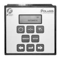
1A
AUTOMATIC
× -ãããããáÜÜÜÜ+
STROKE LIMIT

 Loading...