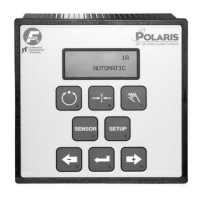
DP-20 WEB GUIDE CONTROLLER ADDITIONAL USER MANUAL INSTRUCTIONS
05-14-2004 DP-20 WEB GUIDE CONTROLLER Figure Sheet 1-875
1
1-1
1 GENERAL INFORMATION
NOTE: The information in this document supplements or supersedes that which is listed in the
Polaris DP-20 Web Guide Controller User Manual, Figure Sheet 1-862.
Explaination of Additional Features
GUIDE POSITION FEEDBACK
The guide position feedback is provided by the customer supplied 10K potentiometer (with a
1.91K resistor in series). This potentiometer also provides feedback for the Servo Center
feature of the Polaris DP-20.
HARDLOCK
The purpose of the Hardlock feature is to maintain the guide position in Manual mode. Hardlock
is active while in the Setup Menus if the Setup Menus were entered while in Manual mode.
Hardlock is disabled during Auto Setup. Hardlock uses the same guide position feedback as
Servo Center. Therefore, the Servo Center Calibration must be performed and Servo Center
Polarity must be set before Hardlock can be used. The Servo Center Gain is set to 25% at the
factory. If it is desired to change this gain setting, refer to the procedure “3X.1.6 Servo-Center
Gain” in the Polaris DP-20 Web Guide Controller User Manual.
STROKE LIMITS
The purpose of Stroke Limits is to restrict the movement of the guide to within two limits, which
are programmed using the Set Stroke Limits procedure. The Stroke Limits use the same
potentiometer for guide position feedback, as does Servo Center. Therefore, the Servo Center
Calibration must be performed and Servo Center Polarity must be set before Stroke Limits can
be set and used. The Servo Center Calibration determines the range of adjustment of the
Stroke Limits.
During operation, when the guide reaches either Stroke Limit, the guide will stop moving and
“STROKE LIMIT” begins flashing on line 4 of the LCD Panel. Also, Output B of the Digital I/O is
turned on. The guide is not allowed to continue moving in the direction of the Stroke Limit. The
proper jog key may be used to move the guide in the opposite direction from the Stroke Limit.
While in Automatic mode or Servo Center mode, the guide will move in the opposite direction
from the Stroke Limit if the error signal is of the correct polarity for movement in that direction.
When the guide moves away from the Stroke Limit, Output B of the Digital I/O is turned off.
MOTOR DETECTION
The first time that a 442K ohm resistor is detected in the drive cable
during power-up, the LCD Panel will display ACTIVATING
ALTERNATE MATRIX on lines 2 and 3, and PRESS
èéê on line 4, until
the Enter key is pressed. After the ENTER key is pressed, the unit will
automatically restart. During the restart, the alternate matrix is loaded
and the Hardlock and Stroke Limit menus are enabled.
ACTIVATING
ALTERNATE MATRIX
PRESS èéê

 Loading...